
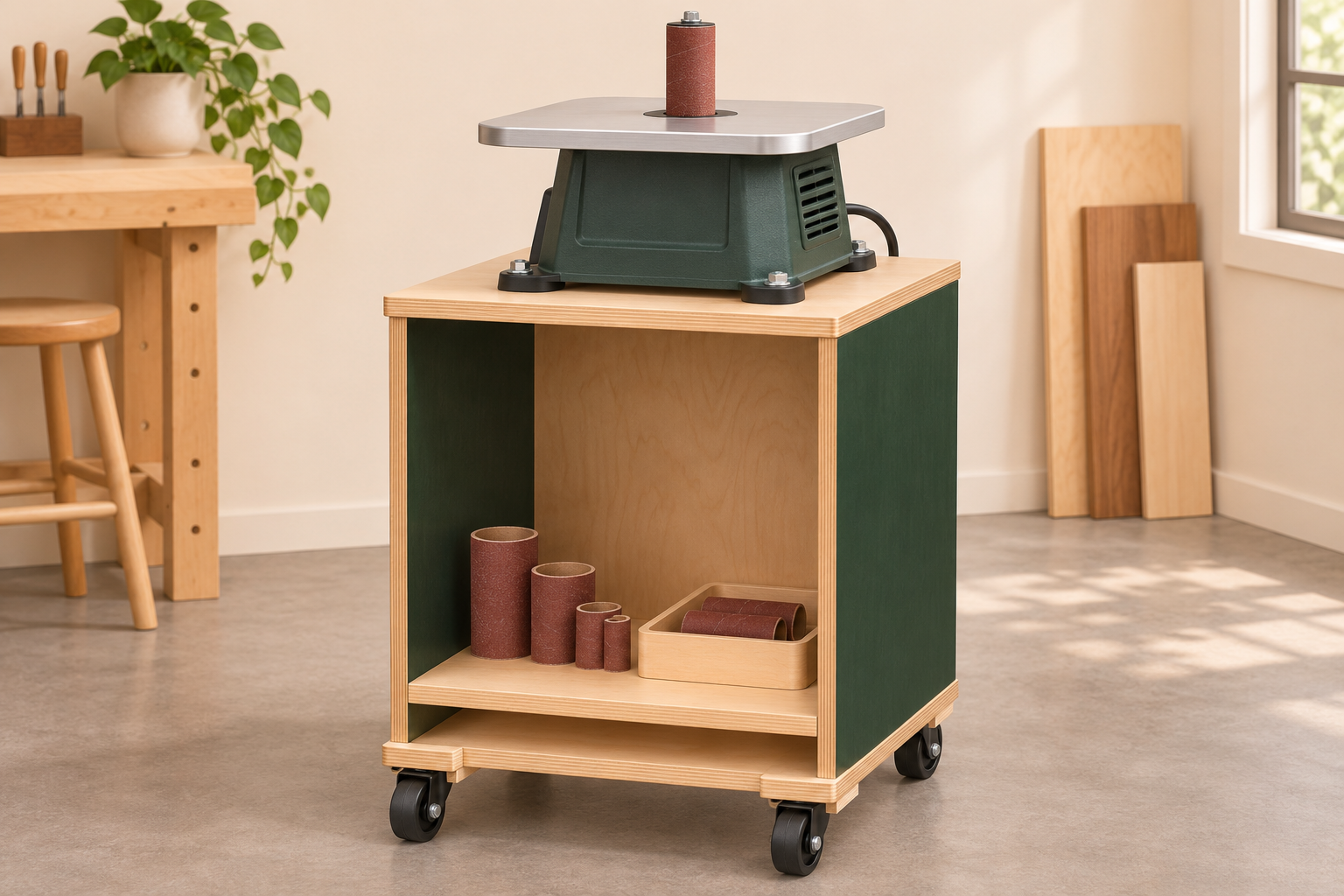
Design in development — not reviewed or build tested.
Materials and hardware
- One 4 × 8 sheet of 3/4-inch plywood
- One 8-foot 1×2 board (actual 3/4 × 1 1/2)
- Four dual-locking plate casters
- Wood screws, glue, caster and machine mounting bolts
Required tools
- Circular saw with straightedge or track guide
- Drill and driver with pilot and clearance bits
- Clamps, square and tape measure
- Wrenches for mounting hardware
- Sandpaper
Fit checks and limitations
24 × 24-inch top. Example finished height 34 inches with a 5-inch caster-and-pad assembly. Check actual machine mounting, stability, operating clearance and manufacturer requirements.
A dedicated home for your spindle sander
Free your main workbench without putting the sander away after every session. This compact plywood cabinet holds a small benchtop spindle sander on a replaceable top, with a low shelf for sanding sleeves and accessories. Roll it into position, secure it for use, and store it along the wall when finished.
What this version does: provides a 24 × 24-inch mounting surface, an open accessory shelf and a full back to resist cabinet racking. The example is 34 inches high to the stand top, including casters; the sander’s own table sits higher. Choose your working height at the machine table, not just the cabinet top.
Check your machine before buying materials
- Read the sander manufacturer’s mounting instructions. Use this design only if a mobile wooden stand is permitted; follow any anchoring requirements. This is not a universal machine base for planers, miter saws or heavy machinery.
- Make a full-size 24 × 24-inch paper template. Place the machine, mark its mounting holes, and check access to switches, vents, belt or spindle changes and dust ports. Keep the machine centered and its feet fully supported; a footprint that fits does not establish safe operating clearance.
- Check the mounting pattern against the top cleats and side/back panels below. Leave space for bolt heads, washers, nuts and a wrench. Adjust the pattern or reject the fit before cutting.
- Measure floor-to-machine-table height on your preferred work surface. Subtract the machine’s base-to-table height to choose the stand height. Check stock clearance around the station and hose/cord routing.
Cut list
All dimensions are inches. Dimensions assume actual 3/4-inch plywood and actual 3/4 × 1 1/2-inch cleats. Measure your stock first; thinner plywood changes the interior opening, shelf fit and finished height. Cut the shelf after assembling the cabinet.
| ID | Part | Qty | Finished size |
|---|---|---|---|
| A | Top + base | 2 | 24 × 24 × 3/4 |
| B | Sides | 2 | 27 1/2 H × 22 1/2 D × 3/4 |
| C | Back, between sides | 1 | 27 1/2 H × 22 1/2 W × 3/4 |
| D | Shelf | 1 | 22 3/8 W × 21 5/8 D × 3/4 |
| E | Caster strips | 2 | 24 L × 4 W × 3/4 |
| F | Cleats | 4 | 20 1/2 L × 1 1/2 H × 3/4 |
Height adjustment: side and back height = target stand height − measured caster assembly height − twice the plywood thickness. Caster assembly means the actual installed caster plus its reinforcing strip, including any spacers. Example: 34 − 5 − 1 1/2 = 27 1/2 inches. Use the same height for both sides and the back. This plan uses manual measurements rather than the assembly-table calculator.
Drawings and sheet breakdown
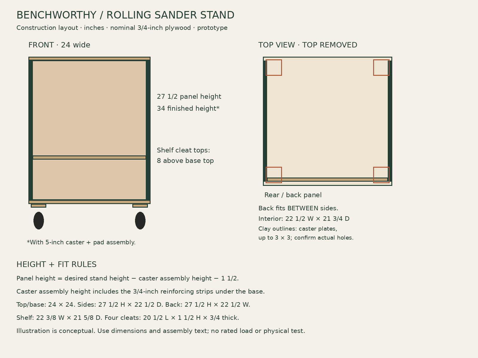
One full 48 × 96-inch sheet can supply the plywood parts, allowing a 1/8-inch saw kerf. Rip one 24-inch-wide strip; the remainder is about 23 7/8 inches wide. From the 24-inch strip crosscut two 24-inch top/base blanks, one 27 1/2-inch panel blank and two 4-inch caster strips. From the remaining strip crosscut two 27 1/2-inch panel blanks and one 21 5/8-inch shelf blank. Trim the three panel blanks to 22 1/2 inches wide and the shelf to 22 3/8 inches. Mark parts first; allow extra stock if your sheet needs edge squaring or is undersized. One 8-foot 1×2 supplies the four cleats.
Hardware and fastening
- Wood glue suitable for plywood; approximately 50 #8 × 1 3/4-inch wood screws for carcass and top, plus 16 #8 × 1 1/4-inch screws for the four cleats. Use pilot holes sized to the screw and plywood. These screws are not drywall screws.
- Four plate-mounted casters with wheel AND swivel locks, plates no larger than 3 × 3 inches for the illustrated layout. Select hardware for the actual loaded stand; do not infer a cabinet load rating from caster ratings. Measure installed caster height before cutting the panels.
- Sixteen caster through-bolts if the chosen plates have four holes each, with washers and locking nuts sized to the actual plates. Bolt length must accommodate the plate, 1 1/2 inches of plywood, washers and full nut engagement. Check the manufacturer’s bolt specification.
- Machine-mounting bolts, washers and locking nuts matching the machine manual. Determine length from the actual foot/casting and 3/4-inch top; do not guess or drill into the machine body.
Build sequence
- Cut A, B, C, E and F; label the front edges. Sand exposed edges and ease sharp corners. Dry-fit the sides on the base with their outside faces flush to its left and right edges. Center each 22 1/2-inch side depth on the 24-inch base, leaving 3/4 inch at front and rear.
- Fit the back between the sides, with its rear face flush to the side rear edges. Glue these three vertical joints to the base and each other. Clamp square and compare cabinet diagonals. Drive five 1 3/4-inch screws through the base into each side bottom and four into the back bottom. Drive four through each side into the back edge. Pilot on the plywood edge centerline and avoid intersecting screws.
- Fasten two cleats inside the sides with their tops flush with the side tops. Center each 20 1/2-inch cleat along the interior depth, clear of the back. Use glue and four 1 1/4-inch screws per cleat through the cleat into the panel face; confirm the points do not emerge.
- Install the other two cleats with their top edges 8 inches above the base’s upper face. Use the same glue and four-screw attachment. Measure the assembled opening. Cut the shelf about 1/8 inch smaller in each direction than that opening, leaving about 1/16 inch around each edge. It rests on the cleats and lifts out for access.
- With the cabinet safely supported upside down, glue the two caster strips beneath the base, flush to the left and right edges and running front to rear. Clamp until cured. Lay out the actual caster plates near the corners; nominal plate centers are 2 inches from each adjacent edge. Confirm all holes pass through BOTH strip and base, clear the side/back bearing lines and allow full swivel clearance. Through-bolt each plate; keep washers and nuts accessible inside the cabinet.
- Fit the top with left/right edges flush to the sides and 3/4-inch front/rear overhang. Do not glue it. Attach with four 1 3/4-inch screws per top cleat from above, centered on the cleat width and away from machine bolts. Predrill to avoid splitting.
- Apply the finish and allow it to cure. With the machine unplugged and the shelf removed, bolt the machine through the top following its manual; reinstall the shelf. Route the cord and dust hose to the rear without pinching them or leaving them in the caster path.
Before putting it to work
Unreviewed prototype — not build tested. The dimensions and sheet breakdown have been checked digitally, but cabinet strength, machine vibration and stability have not been physically validated. No load capacity is claimed. The render shows the intended use; caster details and shelf height may differ from the construction drawing.
- Check cabinet squareness, joints, caster bolts, top screws and machine fasteners before use. All four casters must contact a flat floor.
- Lock both wheel and swivel mechanisms before use. If the station moves, rocks or vibrates, stop; caster locks alone do not establish stability. Follow the machine manual’s requirements for a fixed base or anchoring.
- Move the station only with the machine off and unplugged, accessories secure, and hoses disconnected. Push low on the cabinet rather than pulling the machine. Do not move across steps, slopes or floor obstacles.
- Validate the completed stand with the intended machine before treating this prototype as a finished, tested plan.