
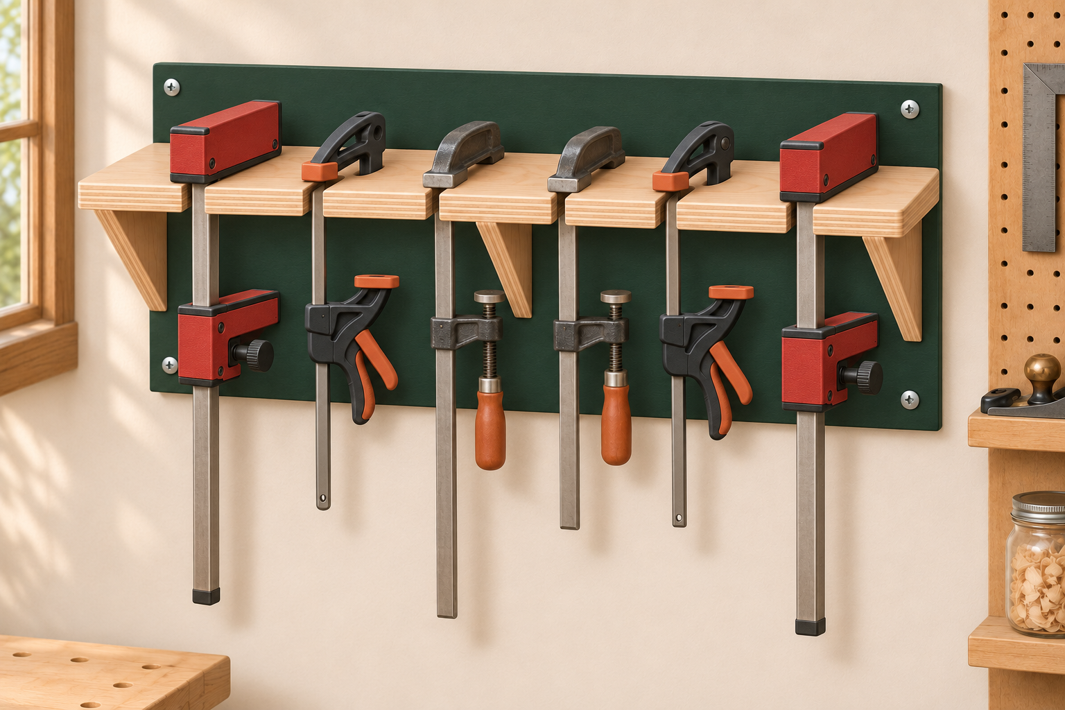
Design in development — not reviewed or build tested.
Materials and hardware
- One 24 × 48-inch panel of actual 3/4-inch sound plywood
- Wood glue and wood screws
- Four structural washer-head stud-mounting screws
Required tools
- Circular saw with straightedge
- Jigsaw suitable for 1 1/2-inch plywood
- Drill and driver with 3/8-inch and pilot bits
- Clamps, square, level and tape measure
- Stud finder and sandpaper
Fit checks and limitations
Six 3/8-inch slots for compatible F-clamps with bars no thicker than 1/4 inch and fixed-head bearing width at least 7/8 inch across the slot. Test actual clamp heads in scrap. Wood studs 16 inches on center only.
Keep six F-clamps visible and within reach
This wall-mounted rack stores six compatible F-style bar clamps individually. Slide each bar into an open-front slot; its upper fixed jaw rests on the shelf while the bar and movable jaw hang below. You can take one clamp without unpacking a pile, and empty slots show what is missing.
A double-thickness plywood shelf is supported by three triangular gussets. The backboard spans two studs on 16-inch centers. Allow clear wall space below for the longest clamp and enough space above to lift each clamp free. The rack is storage, not a surface to tighten clamps against.
Test your clamps first
- The updated hero illustration shows a mixed-clamp storage concept. The current construction dimensions are for compatible F-clamps; parallel and quick clamps require separate slot-fit and support validation. This version is for smaller F-style clamps with a flat steel bar no more than 1/4 inch thick in the slot-width direction. Orient the bar’s broad face front-to-back. The 3/8-inch slot provides clearance; it is not a universal clamp holder.
- The fixed head must bridge the slot with at least 1/4 inch of bearing on each side: at least 7/8 inch of solid head width across the slot. Irregular, rounded or sloping heads may not seat safely even when that width fits.
- Make one 3/8-inch slot in a 1 1/2-inch laminated scrap first. Check the actual head sits flat, the bar slides without force, and the clamp can lift out without catching. Test all clamp models you intend to store.
- Slot centers are 4.8 inches apart. Check adjacent jaws and handles do not collide and that the head clears the backboard. Use fewer slots if needed; do not widen slots or lengthen them without redesigning the rack. Pipe clamps, large parallel-jaw clamps, spring clamps and quick-grip shapes are outside this plan’s fit assumptions.
Cut list
Dimensions are inches and assume actual 3/4-inch plywood. Use sound, void-free plywood around slots and fasteners. A 24 × 48-inch project panel can supply these parts if its usable dimensions and trimming allowance permit; lay out all cuts before sawing.
| ID | Part | Qty | Size |
|---|---|---|---|
| A | Backboard | 1 | 32 × 10 × 3/4 |
| B | Shelf layers | 2 | 32 × 6 × 3/4 |
| C | Gusset blanks | 3 | 4 1/2 × 4 1/2 × 3/4; cut diagonally |
Use one triangle from each gusset blank; keep the other halves as spares. For a 24 × 48 panel, crosscut a 32-inch-long section and rip the 10-inch back and two 6-inch shelf layers from its 24-inch width (22 inches plus kerfs). The remaining approximately 15 7/8 × 24-inch section supplies the gusset blanks. Confirm saw kerf and actual panel size first.
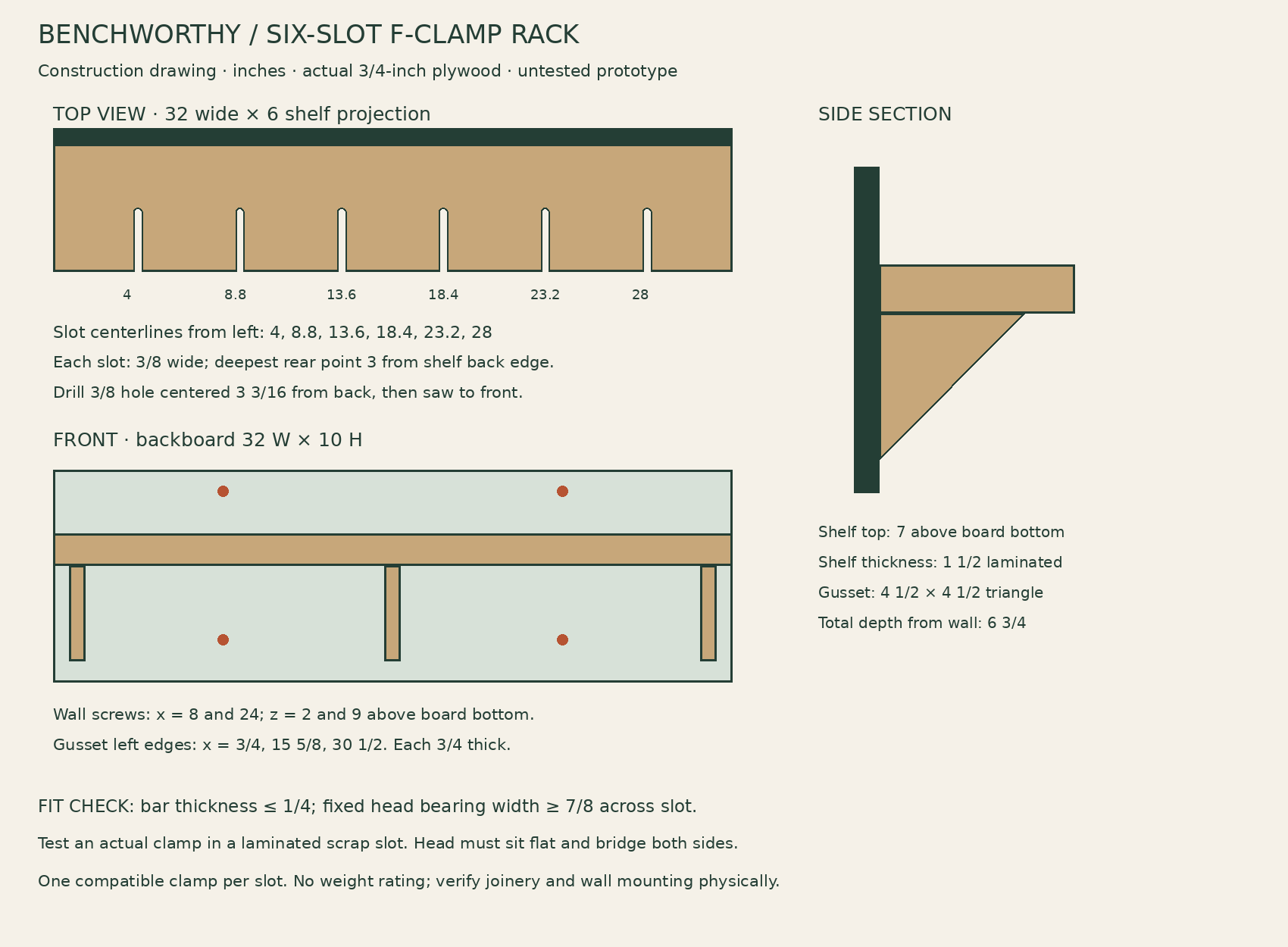
Construction drawing
Hardware and wall mounting
- Wood glue; six #8 × 1 1/4-inch wood screws to retain the shelf laminations while gluing; nine #8 × 1 3/4-inch screws through the back into gussets; nine #8 × 2 1/2-inch screws through the shelf into gussets; six #8 × 1 3/4-inch screws through the back into the laminated shelf rear edge. Use suitable wood screws and pilot holes; do not substitute drywall screws.
- Four washer-head structural wood screws approved by their manufacturer for attachment to wood studs, with at least 1 1/2 inches of stud penetration after the 3/4-inch backboard and wall finish. For 1/2- to 5/8-inch drywall, 3-inch screws provide 1 5/8 to 1 3/4 inches of geometric penetration; confirm the selected product’s installation requirements and usable threaded embedment.
- The illustrated wall has sound wood studs 16 inches on center with drywall no thicker than 5/8 inch. Mount screw columns at 8 and 24 inches from the board’s left edge, with rows 2 and 9 inches above its bottom. Verify stud centers and hidden services before drilling. Do not use drywall-only anchors. Masonry, metal studs, different spacing or damaged walls need a separate attachment design.
Build and install
- Cut and label all blanks. Cut three right-triangle gussets, each with 4 1/2-inch perpendicular legs. Sand sharp edges. Keep the square edges flat so the gussets bear against both back and shelf.
- Glue the two shelf layers face-to-face, aligning their edges. Clamp flat with cauls. Add six 1 1/4-inch screws from the underside at x = 2, 16 and 30 inches, in rows 1 and 2 inches from the rear. Predrill and countersink flush; these positions clear the slots and gussets. Allow the glue to cure before cutting slots.
- Mark the six slot centerlines 4, 8.8, 13.6, 18.4, 23.2 and 28 inches from the left edge. Drill a 3/8-inch through-hole at each centerline, with its center 3 3/16 inches from the shelf’s rear edge. Saw two parallel lines from the front edge tangent to each hole, making a 3/8-inch-wide open slot. The deepest slot point is 3 inches from the rear. Support the work and use a blade suitable for the 1 1/2-inch thickness. Smooth the slots without enlarging them.
- On the backboard front, mark a line 5 1/2 inches above the bottom: this is the shelf underside. Mark gusset left edges at 3/4, 15 5/8 and 30 1/2 inches from the left. Each gusset’s upper horizontal leg aligns with that underside line, and its rear vertical leg runs down to 1 inch above the board bottom. Dry-fit and clamp the assembly square.
- Glue each gusset rear edge to the backboard. Drive three 1 3/4-inch screws through the back into each gusset edge, centered on its 3/4-inch thickness, at heights 2 1/4, 3 1/4 and 4 1/2 inches above the board bottom. Use correctly sized pilots and keep screw axes straight in the plywood edges. Let the glue cure with the supports clamped square.
- Glue the shelf onto the gussets with its rear edge against the backboard. Its top is now 7 inches above the backboard bottom. Drive three 2 1/2-inch screws down through the shelf into each gusset, centered across the gusset thickness, at 1 1/2, 2 1/2 and 3 1/4 inches forward of the shelf rear edge. Avoid the previously installed rear screws; the stated screw positions occupy different depths. Add six 1 3/4-inch screws through the back into the shelf rear edge at x = 2, 7, 12, 20, 25 and 30 inches, centered vertically in the 1 1/2-inch shelf thickness.
- Ease edges, finish and allow glue and finish to cure. With a helper supporting the empty rack, locate the two stud centers, level the rack and mark the four mounting holes. Drill clearance holes through the backboard and stud pilots according to the structural screw manufacturer. Fasten all four screws securely without crushing the plywood or wall finish.
- Try each intended clamp separately, supporting its weight by hand as you check seating and clearance. Store one clamp per slot, with the fixed head resting flat across both sides. Keep the full hanging length clear of benches, doors, outlets and walkways.
Prototype checks and limits
Unreviewed prototype — not build tested. The part layout, slot clearances and nominal screw locations have been checked digitally. Shelf fingers, glued joints, plywood edge fasteners and wall attachment have not been physically load tested. Six slots describe storage positions, not a weight rating. The concept render explains how the clamps hang; use the drawing for shelf height, slot geometry and mounting positions.
- Inspect for split slot fingers, plywood voids, loose joints and wall movement before adding clamps. Stop using the rack if any part flexes, cracks or loosens.
- Do not stand on the shelf, add a second row, stack clamps in a slot or use it for active clamping. Keep heavy or incompatible clamps on a separately designed support.
- A physical prototype and wall-attachment verification are still required before this plan can be marked build tested.