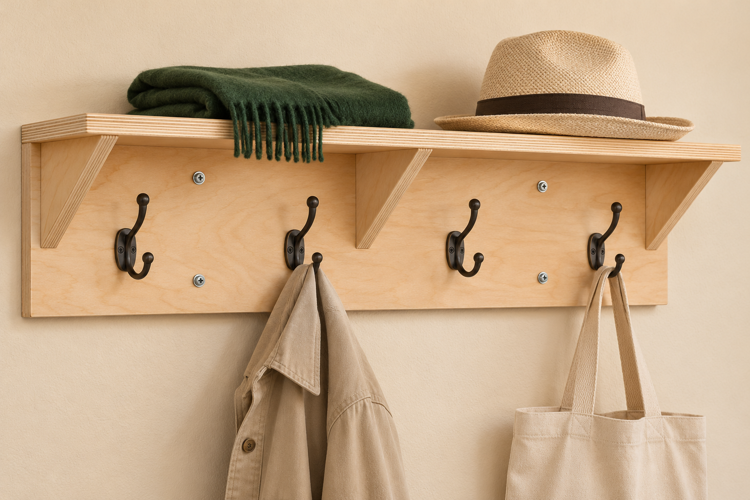
Hang four everyday coats or bags beneath a shallow shelf for hats and small entryway items. Three triangular brackets support the shelf while keeping the hook spaces open. The backboard mounts to two wood studs 16 inches apart.
Check the fit
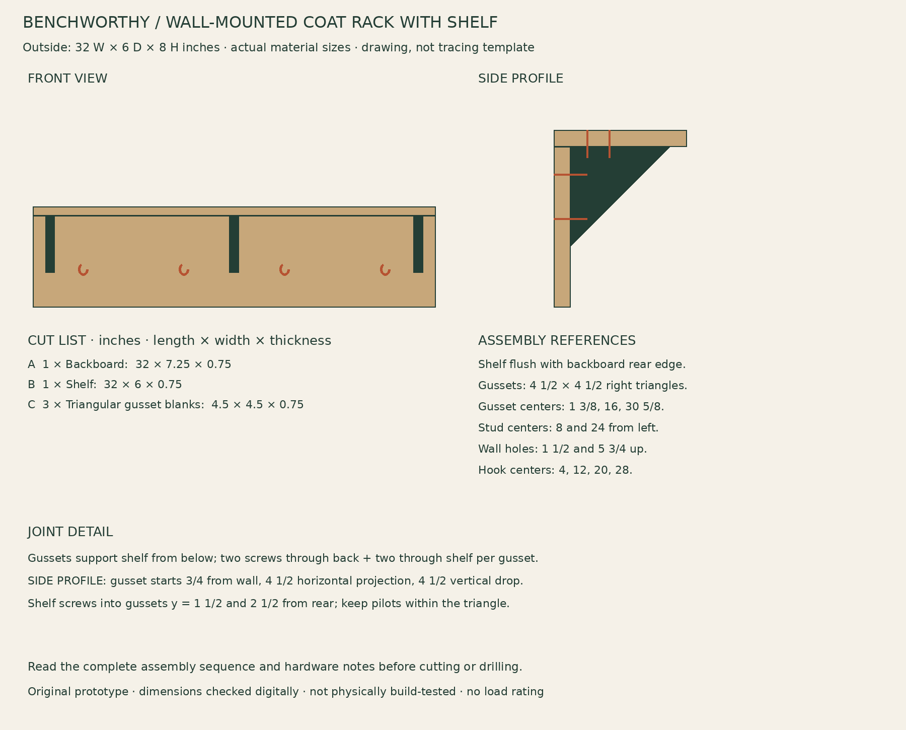
Overall 32 inches wide, 6 inches from wall to shelf front, 8 inches high. Shelf top is 3/4 inch above the backboard.
This mounting layout is for two sound wood studs at 16 inches on center behind 1/2- or 5/8-inch drywall. It does not cover hollow-wall anchors, masonry or metal studs.
Choose hook bases that fit the 7 1/4-inch backboard and have screw positions clear of the gussets and wall fasteners. Lay the actual hooks out before drilling.
Materials and tools
One 24 × 48-inch panel of actual 3/4-inch sound plywood
Four two-hole coat hooks whose bases fit below the shelf; use eight hook screws suited to 3/4-inch plywood without breaking through the back
Four 3-inch washer-head structural wood screws, selected for wood-stud mounting and the actual wall; minimum 1 1/2-inch embedment into sound studs, excluding drywall and backboard
Tools: Circular saw with guide; jigsaw for gusset diagonals; Drill/driver, pilot and clearance bits, countersink and depth stop; Clamps, square, level, tape measure and stud finder.
Cut list
Part
Qty
Length
Width
Thickness
A — Backboard
1
32 in
7.25 in
0.75 in
B — Shelf
1
32 in
6 in
0.75 in
C — Triangular gusset blanks
3
4.5 in
4.5 in
0.75 in
Drawings and connections
Use stated dimensions and actual material thickness. Concept images illustrate use; this drawing and the instructions define construction.
Shelf sits on top of the backboard, flush at the wall-side rear edge. Gussets meet the backboard front face and shelf underside. Their horizontal and vertical legs are each 4 1/2 inches.
Gusset centerlines: x = 1 3/8, 16, 30 5/8 inches from left. Glue mating faces. Two 1 1/2-inch screws enter each gusset from the BACK at z = 4 and 6 inches above backboard bottom.
Four 1 1/2-inch screws through shelf into backboard top edge: x = 4, 12, 20, 28; y = 3/8 from wall-side shelf edge. Six 1 1/4-inch screws through shelf into gussets: at each gusset centerline, y = 1 1/2 and 2 1/2 from rear. These positions stay within the triangular wood beneath.
Wall fasteners: x = 8 and 24, z = 1 1/2 and 5 3/4 inches from backboard bottom. Verify actual stud centers before drilling. Three-inch screw less 3/4 backboard and 5/8 drywall leaves 1 5/8 inches nominal stud penetration; follow the screw maker’s requirements.
Hook centerlines: x = 4, 12, 20, 28. Set actual hook bases near z = 3 inches, adjusting to their hole pattern. Do not let hook screws penetrate the wall or collide with other screws.
Assembly
Cut the plywood. Cut the backboard and shelf square. Cut three 4 1/2-inch-square blanks and divide each diagonally, using one triangle from each; keep the spare halves. Support and clamp small blanks safely while cutting.
Lay out the hardware. Dry-fit shelf, three gussets and actual hooks. Mark all screw locations from the joint notes and check interference. Do not mark hook holes from a generic drawing; use the selected hook bases.
Build the shelf assembly. Glue shelf to backboard and clamp square. Drill clearance holes through shelf and pilots into the backboard edge, then drive the four top screws. Glue gussets into position; fasten through the back first, then through the shelf. Keep heads on the rear flush so the rack seats flat.
Finish and add hooks. Allow glue cure, ease corners and sand. Apply and cure finish. Pilot hook holes with a depth stop and install the hooks using screws that fit the plywood thickness. Verify tips do not protrude from the rear.
Mount to studs. Locate and verify two sound stud centers 16 inches apart and check for services before drilling. Level the rack, transfer mounting holes and pilot as required by the structural screw maker. Fasten all four wall screws with the rack supported; do not crush the backboard. If stud spacing or wall construction differs, stop and use a separately designed mounting detail.
Check before use. Check shelf joints, hooks and all wall fasteners, then add ordinary items gradually. Stop for movement, splitting or loose hardware. Do not assign a capacity from the hook packaging alone; the entire assembly and wall connection matter.
Use and care
Do not use as a grab bar, climbing aid or support for a person.
Keep heavy or breakable objects off the shallow shelf. No assembly load rating is established.
Periodically inspect mounting screws, hook screws and gusset joints.
Build notes
This original plan has not been physically build-tested. Digital checks cover dimensions and part fit; they do not establish joint strength, load capacity or long-term performance. Check the actual materials and hardware, dry-fit before fastening, and stop use if joints loosen or parts deform.
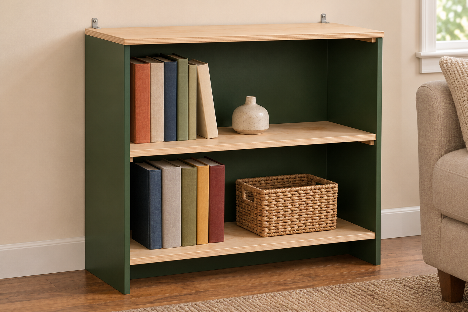
A 30-inch-tall bookcase keeps books and small baskets within easy reach. Two fixed shelves and a full plywood back create a simple open-front cabinet. Secure it to wall studs before loading; its low height does not make it tip-proof.
Check the fit
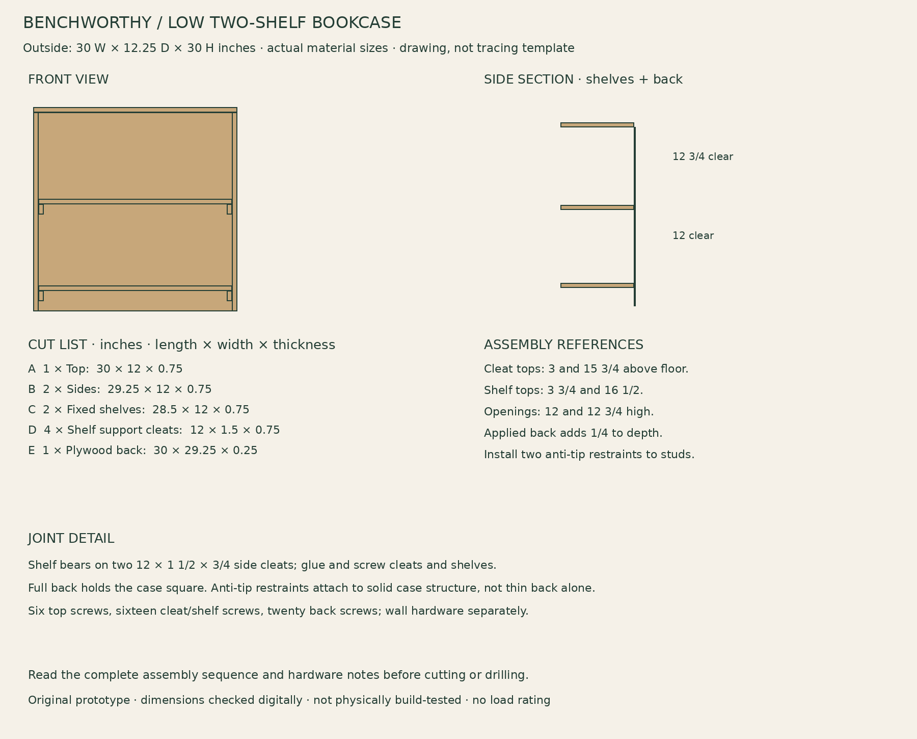
Outside 30 W × 12 1/4 D × 30 H inches including the applied back. Clear shelf width 28 1/2 inches.
Lower shelf top is 3 3/4 inches above the floor; upper shelf top is 16 1/2. Clear opening heights are 12 inches below the upper shelf and 12 3/4 inches below the top.
Select a level wall location with access to wood studs and check any baseboard gap against the anti-tip hardware instructions. This plan does not specify drywall-only anchoring.
Materials and tools
One 4 × 8-foot sheet of actual 3/4-inch plywood
One 4 × 4-foot sheet of actual 1/4-inch plywood for the back
Two furniture anti-tip restraints with wall and furniture fasteners specified by their maker for this construction
Tools: Circular saw with guide and full sheet support; Drill/driver, pilot/clearance bits, countersink and depth stop; Clamps, square, level, tape measure and stud finder.
Cut list
Part
Qty
Length
Width
Thickness
A — Top
1
30 in
12 in
0.75 in
B — Sides
2
29.25 in
12 in
0.75 in
C — Fixed shelves
2
28.5 in
12 in
0.75 in
D — Shelf support cleats
4
12 in
1.5 in
0.75 in
E — Plywood back
1
30 in
29.25 in
0.25 in
Drawings and connections
Use stated dimensions and actual material thickness. Concept images illustrate use; this drawing and the instructions define construction.
Sides are 29 1/4 inches tall; the 3/4-inch top caps them. Shelf boards fit between the sides. Back covers the rear below the top and adds 1/4 inch to depth.
Each 12-inch cleat lies on edge against an inside side face: 1 1/2 inches tall, projecting 3/4 inch. Cleat TOP elevations are 3 and 15 3/4 inches from the floor.
Two #8 × 1 1/4 screws per cleat, through cleat into side, at 3 and 9 inches from front; keep pilots centered vertically. Two more per shelf end, down through shelf into cleat, at 4 and 8 inches from front. Glue both contacts.
Top: three #8 × 1 1/2 screws into each side top edge, at 2, 6 and 10 inches from front. Back: five #6 × 1 screws into each side rear edge, five into each shelf rear edge; keep 2 inches away from corners and space evenly. Pre-drill plywood edges.
Cut five 12-inch crosscut bands from the 8-foot sheet length; take one top, two sides and two shelves across those bands. Measure each new band after the preceding kerf.
Assembly
Cut and inspect. Cut the top, sides, shelves and back square. Match side lengths and shelf lengths. Cut four cleats from the 1×2; use the 6-foot stock to leave kerf allowance. Reject delaminated plywood or split cleats.
Attach shelf supports. Lay the sides inside-face up. Mark cleat tops at 3 and 15 3/4 inches from the bottom. Glue, clamp and screw the cleats to the sides with the specified pilot and clearance holes. Keep each pair level with its mate.
Assemble the cabinet. Stand the sides upright, place the shelves on the cleats and clamp to the 30-inch outside width. Glue and screw shelves down to the cleats. Cap with the top, drill pilots into side top edges and drive six top screws. Do not overdrive.
Square with the back. Lay the cabinet face down on padded supports. Check equal diagonals across the rear, then glue and screw on the 30 × 29 1/4 back flush to side edges and bottoms. Mark shelf elevations on the back before drilling. The back must be attached before standing the case.
Finish and restrain. Allow adhesive cure, sand and finish. Put the empty case in its final level position. Install two compatible anti-tip restraints to sound side/top structure and wall studs exactly as their manufacturer directs; do not fasten furniture-side restraints only to the thin back.
Load gradually. Check joints and restraints, then add books gradually with heavier items on the lower shelf. Stop for sagging, movement, loose fasteners or cracking. No shelf load rating has been established.
Use and care
Do not climb, sit or stand on the bookcase. Keep tempting items off the top where children could climb for them.
Recheck anti-tip attachments after moving and periodically in use. Empty before moving.
The plywood back braces the case; it does not replace wall restraints.
Build notes
This original plan has not been physically build-tested. Digital checks cover dimensions and part fit; they do not establish joint strength, load capacity or long-term performance. Check the actual materials and hardware, dry-fit before fastening, and stop use if joints loosen or parts deform.
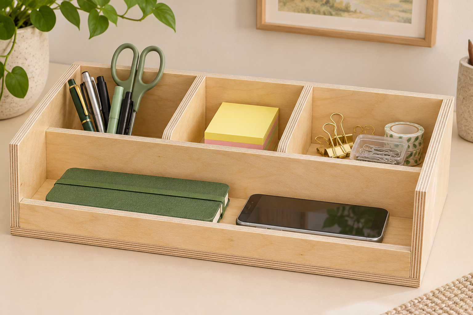
Keep a notebook or phone in the front trough and separate pens, scissors and small supplies in three rear compartments. This desktop caddy is assembled from straight plywood pieces with glued joints; it stays on the desk rather than serving as a carry box.
Check the fit
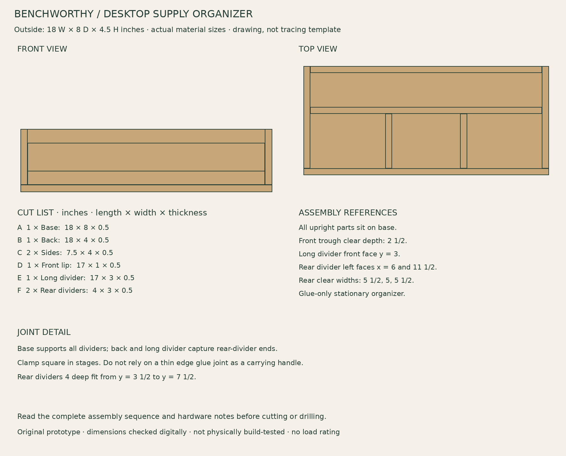
Outside 18 × 8 × 4 1/2 inches. Front trough: 17 × 2 1/2 inches clear. Rear compartments: 5 1/2, 5 and 5 1/2 inches wide, each 4 inches deep.
A phone rests in the trough; there is no angled charging stand or cable opening.
Cut a full-size paper layout and check your notebook and supplies before cutting wood.
Materials and tools
One 24 × 24-inch panel of actual 1/2-inch plywood with sound edges
Wood glue and masking tape for dry assembly
Optional furniture finish
Tools: Circular saw with guide and support for small parts; Clamps, square, ruler, sanding block and small glue brush.
Cut list
Part
Qty
Length
Width
Thickness
A — Base
1
18 in
8 in
0.5 in
B — Back
1
18 in
4 in
0.5 in
C — Sides
2
7.5 in
4 in
0.5 in
D — Front lip
1
17 in
1 in
0.5 in
E — Long divider
1
17 in
3 in
0.5 in
F — Rear dividers
2
4 in
3 in
0.5 in
Drawings and connections
Use stated dimensions and actual material thickness. Concept images illustrate use; this drawing and the instructions define construction.
All vertical pieces sit on top of the 1/2-inch base. Back covers the full 18-inch rear edge; sides fit in front of it.
Front lip fits BETWEEN sides, flush with front edge. Long divider front face is 3 inches from base front. Rear dividers left faces are 6 and 11 1/2 inches from base left.
Glue base contact edges and meeting vertical edges. No screws enter the thin plywood edges. Clamp each subassembly until the glue has set; full cure before use.
24 × 24 panel layout: first crosscut an 8-inch band; cut the 18 × 8 base from it. From the remaining panel rip two 4-inch bands, two 3-inch bands and one 1-inch band. Allocate back/sides, long divider/rear dividers, then front lip. Allow saw kerf.
Assembly
Prepare the pieces. Use a supported cutting setup appropriate to small parts; keep hands away from the blade and do not make unsupported tiny cuts. Label the parts and lightly sand inside faces before assembly.
Mark the footprint. On the base mark sides at x = 0–1/2 and 17 1/2–18, back at y = 7 1/2–8, lip at y = 0–1/2, and long divider at y = 3–3 1/2. Mark rear dividers at x = 6–6 1/2 and 11 1/2–12.
Glue the outer shell. Dry-fit all parts first. Glue and clamp the back and sides to the base, keeping the corners square. Fit the 17-inch front lip between the sides. Use a flat reference and clamp pads; let this stage set before adding dividers.
Install the dividers. Glue the 17-inch long divider to the base and sides on its marks. Glue the two rear dividers between it and the back; their front ends start at y = 3 1/2. Clamp gently without bowing the thin panels. Verify the three clear widths.
Finish and organize. Allow full adhesive cure. Ease all touch edges and remove squeeze-out. Finish and cure before adding stationery. Lift the empty organizer under its base; do not pick it up by a divider.
Use and care
Indoor, dry use only. Keep drinks in a separate coaster.
Do not force oversized items into a compartment.
Inspect glued joints periodically; this original assembly has not been physically tested.
Build notes
This original plan has not been physically build-tested. Digital checks cover dimensions and part fit; they do not establish joint strength, load capacity or long-term performance. Check the actual materials and hardware, dry-fit before fastening, and stop use if joints loosen or parts deform.
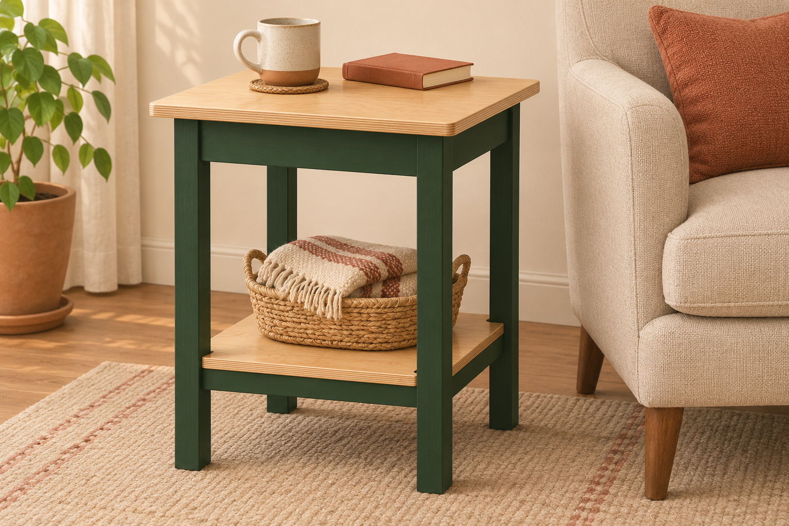
Set a drink and a book beside your chair, with a basket or spare reading material on the lower shelf. This 18-inch-square side table keeps the footprint compact and the storage open. Straight square legs and aprons give it a familiar furniture shape without drawers or complicated joinery.
The plywood top is 24 inches above the floor. A notched lower shelf rests on four rails and is fastened to them to help keep the lower frame square. Upper aprons connect the legs beneath the top. This is indoor occasional furniture; it is not a seat or a step, and no load capacity is assigned.
Check the fit beside your chair
Tape an 18 × 18-inch square beside the chair and compare a 24-inch top height with the chair arm. Confirm you can reach the surface comfortably and still walk around it.
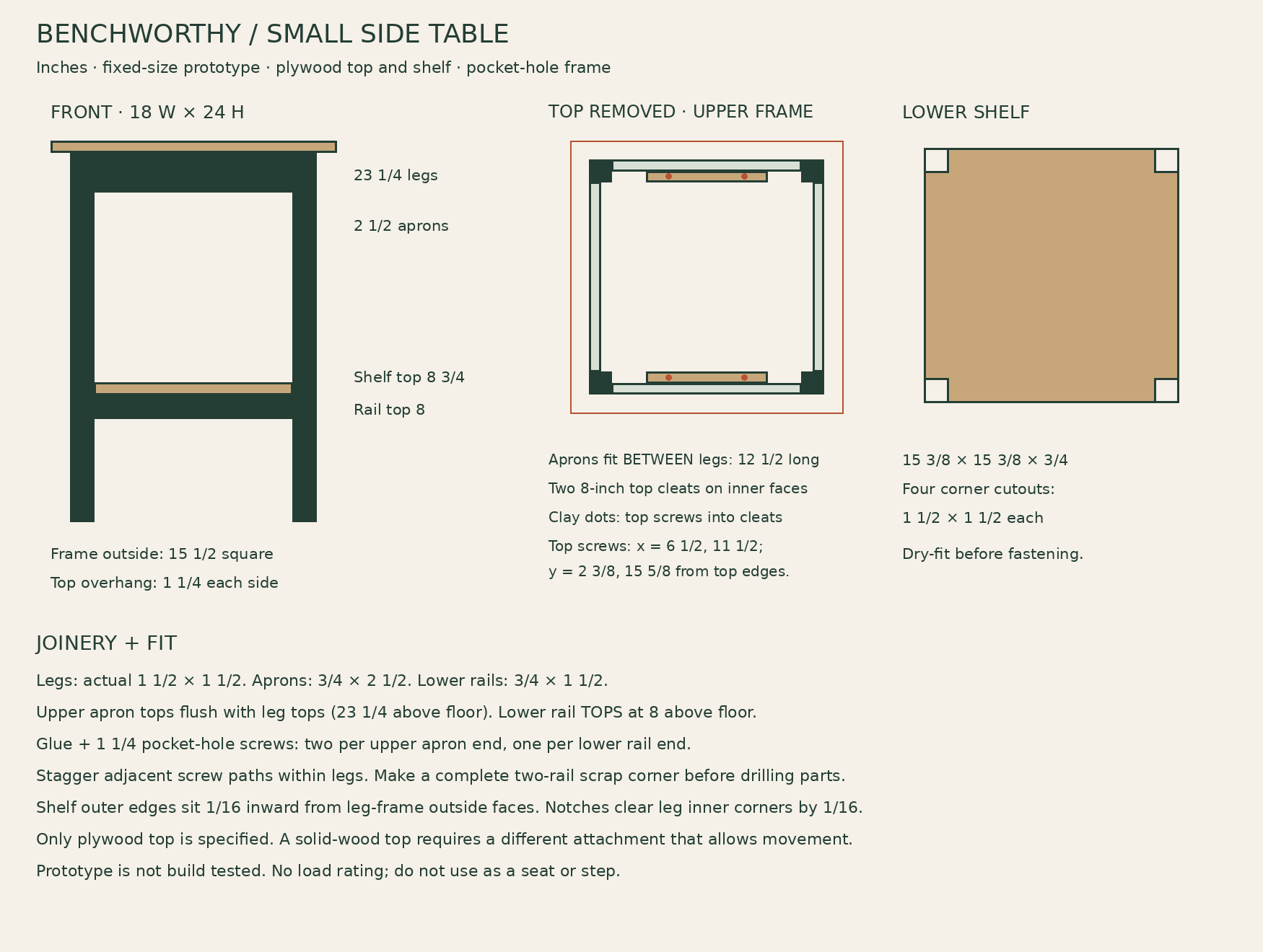
The lower shelf is 15 3/8 inches square before its corner notches. The clear front width between legs is 12 1/2 inches. Clear height from the shelf surface to the upper apron bottom is 12 inches. Choose a basket smaller than both openings, including handles, so it slides out without tilting.
This plan uses a 3/4-inch plywood top. Do not replace it with a solid-wood panel using the same fixed screw pattern; solid wood needs an attachment that permits seasonal movement.
Use dry, straight, square stock and a flat indoor floor. Added feet, a thicker top or tapered legs change the dimensions and stability assumptions.
Cut list
Dimensions are inches. Nominal 2×2 legs must measure 1 1/2 inches square. The 1×3 aprons measure 3/4 × 2 1/2; the 1×2 rails/cleats measure 3/4 × 1 1/2. Verify actual stock before cutting. Leg length = 24 minus top thickness. With the same 15 1/2-inch outer frame, rail/apron length = 15 1/2 minus twice the leg width.
ID
Part
Qty
Size
A
Top
1
18 × 18 × 3/4 plywood
B
Legs
4
23 1/4 × 1 1/2 × 1 1/2
C
Upper aprons
4
12 1/2 × 2 1/2 × 3/4
D
Lower rails
4
12 1/2 × 1 1/2 × 3/4
E
Shelf blank
1
15 3/8 × 15 3/8 × 3/4 plywood
F
Top cleats
2
8 × 1 1/2 × 3/4
Cut a 1 1/2 × 1 1/2-inch square from each shelf corner. With a 15 1/2-inch outside frame and 1 1/2-inch legs, the shelf sits 1/16 inch inside the outside leg faces, with the same nominal clearance at the notch corners. Dry-fit and adjust for actual leg dimensions; do not force the shelf between legs.
Stock allocation: one 24 × 48-inch 3/4-inch plywood panel supplies top and shelf. One 8-foot 2×2 yields four 23 1/4-inch legs with nominal 1/8-inch kerfs. One 6-foot 1×3 supplies four aprons. One 6-foot 1×2 supplies four lower rails and two 8-inch cleats. Allow extra material if ends need more squaring, defects require avoidance, or your stock is undersized.
Construction drawing
Dimensions govern construction. The in-use render shows the intended chair-side storage.
Hardware and pocket-hole setup
Twenty-four 1 1/4-inch pocket-hole screws: sixteen for the upper aprons and eight for the lower rails. Match screw thread to the receiving leg species and follow your jig manufacturer’s settings for actual 3/4-inch material. These are pocket-hole screws with the correct head shape, not ordinary countersunk wood screws.
Eighteen #8 × 1 1/4-inch wood screws: six cleat-to-apron screws, four top-to-cleat screws and eight shelf-to-rail screws. Glue for all frame joints, shelf-to-rail contact and cleat attachment.
Pocket-hole jig, stepped bit, stop collar and driver, plus a joint clamp. Drill on the inside faces. Adjacent rails meet within the same 1 1/2-inch leg, so their screws must be staggered vertically and checked in a complete scrap corner before drilling the parts.
For upper aprons, lay out two hole axes per end. Suggested vertical exit positions are 1/2 and 1 1/2 inches below the top on one opposing pair, and 1 and 2 inches below the top on the adjacent pair. Lower rails use one axis per end, 1/2 inch below the rail top on one opposing pair and 1 inch below on the other pair. Reposition the jig as needed, keep pockets within the rail edges and confirm the actual paths do not meet.
If your jig cannot make these staggered holes cleanly within the stock, stop and revise the joint layout before assembly. A scrap test must show seated screws without split edges, breakthrough or collision.
Manufacturer reference: Kreg pocket-hole setup and screw guidance. Use the instructions for your own jig and actual material; a screw-size chart does not validate this table’s strength.
Build sequence
Cut the four legs together to matching length with square ends. Cut and label the upper aprons, lower rails and cleats. Sand now while the inside faces are accessible. Mark which opposite rail pairs receive each staggered pocket-hole layout.
Make a full scrap corner with two rail ends and a matching leg. Test the jig settings, screw length and staggered entry paths. Inspect for collision and breakthrough. Once the corner works, drill all frame pockets on their inside faces.
Build two opposite side assemblies first. Glue and clamp an upper apron between each leg pair, with its outside face flush to the leg outside faces and its top flush to the leg tops. Glue and attach the lower rail in the same plane, with its TOP 8 inches above the leg bottoms. Drive the pocket screws while the joints are held firmly against a flat reference.
Join these side assemblies with the remaining two upper aprons and two lower rails. Keep each outside face flush with the adjacent leg faces. Confirm the outer frame is 15 1/2 inches square, compare diagonals and clamp square while driving screws. The two lower rail pairs must meet at the same top height. Let the glue cure.
Cut the plywood shelf blank and its four corner notches. Ease the cut edges. With the table top still off, lower the shelf over the legs onto the four lower rails. Check about 1/16-inch clearance from the outside frame faces and around each notch. Trim only as needed so the shelf lies flat without forcing the frame out of square.
Glue the shelf-to-rail contact and add two 1 1/4-inch screws down through the shelf into each rail, centered in the rail’s 3/4-inch thickness and placed away from the pocket screws near its ends. Nominal screw centers are 7 and 11 inches from the tabletop’s left edge on front/rear rails, and 7 and 11 inches from its front on the side rails; use the corresponding shelf position as a reference. Predrill and countersink flush.
Attach one 8-inch cleat to the inside of the front upper apron and one to the rear. Center them along the apron length, with their tops flush with the apron tops. Orient each cleat 1 1/2 inches tall and 3/4 inch thick. Glue and use three 1 1/4-inch face screws per cleat, centered vertically and clear of apron pocket screws. Confirm the tips stay within the apron.
Set the 18-inch plywood top on the frame with 1 1/4-inch overhang on every side. Clamp in place. Drive four 1 1/4-inch screws from above into the top cleats at x = 6 1/2 and 11 1/2 inches from the top left, paired with y = 2 3/8 and 15 5/8 inches from the front. Pilot and countersink flush. Do not drive screws down into unsupported gaps.
Ease the top edges and apply the indoor furniture finish. Allow the finish and glue to cure. Place the table on a flat surface; check all four feet contact the floor, the frame is square and the shelf and top are secure. Use coasters to protect the plywood finish.
Prototype checks and limits
Unreviewed prototype — not build tested. Overall dimensions, cut allocation, shelf-notch clearances and nominal joint layouts have been checked digitally. Pocket-hole paths depend on the actual jig and must be checked in scrap. Joint stiffness, shelf performance and tipping resistance remain untested. No load rating is assigned.
Use only as a small occasional table after checking the physical build for stability. Do not sit, stand or climb on it, or use it to support machinery or heavy concentrated loads.
Keep stored objects within the top and shelf outlines. A small tall table can tip if pulled or heavily loaded at an edge; keep it away from uses where someone would rely on it as a support while standing up.
Inspect for rocking, loose screws, opening joints, split legs and shelf separation. Stop use if these appear. A physical prototype is still required before this plan can be marked build tested.
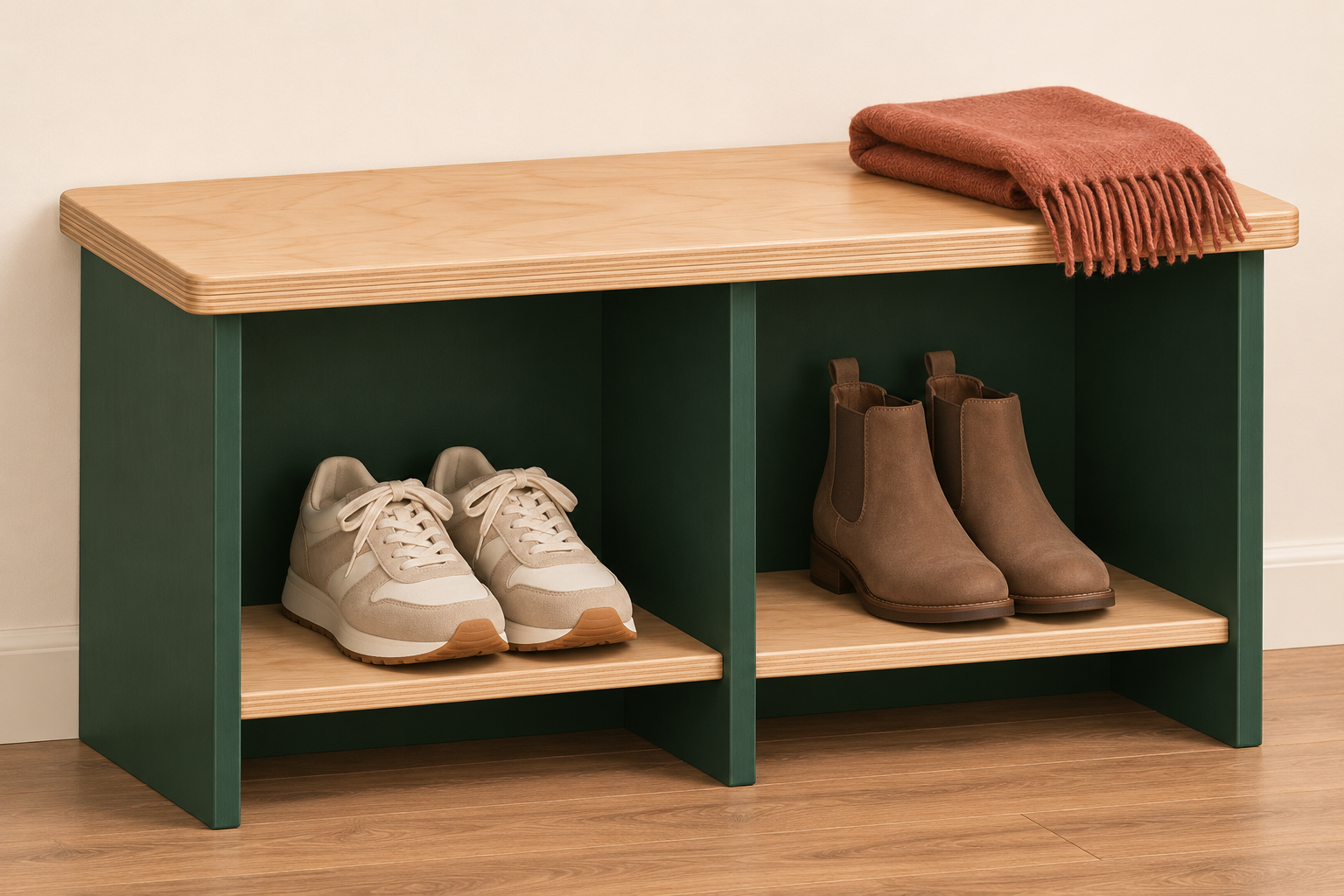
Give the shoes you wear most a place beside the door. This 36-inch-wide bench combines a laminated plywood seat with two open cubbies, each sized for a typical pair of shoes or modest ankle boots after checking your actual footwear. Low shelves lift the shoes off the floor and leave a small cleaning gap underneath.
Two end panels, a center divider and a full back meet the seat underside directly. The divider shortens the unsupported seat spans; the back ties the panels together against racking. The intended use is a place to sit while putting shoes on, but this design is an untested seating prototype and needs physical validation before seating use. No weight rating is assigned.
Check shoe fit and entryway clearance
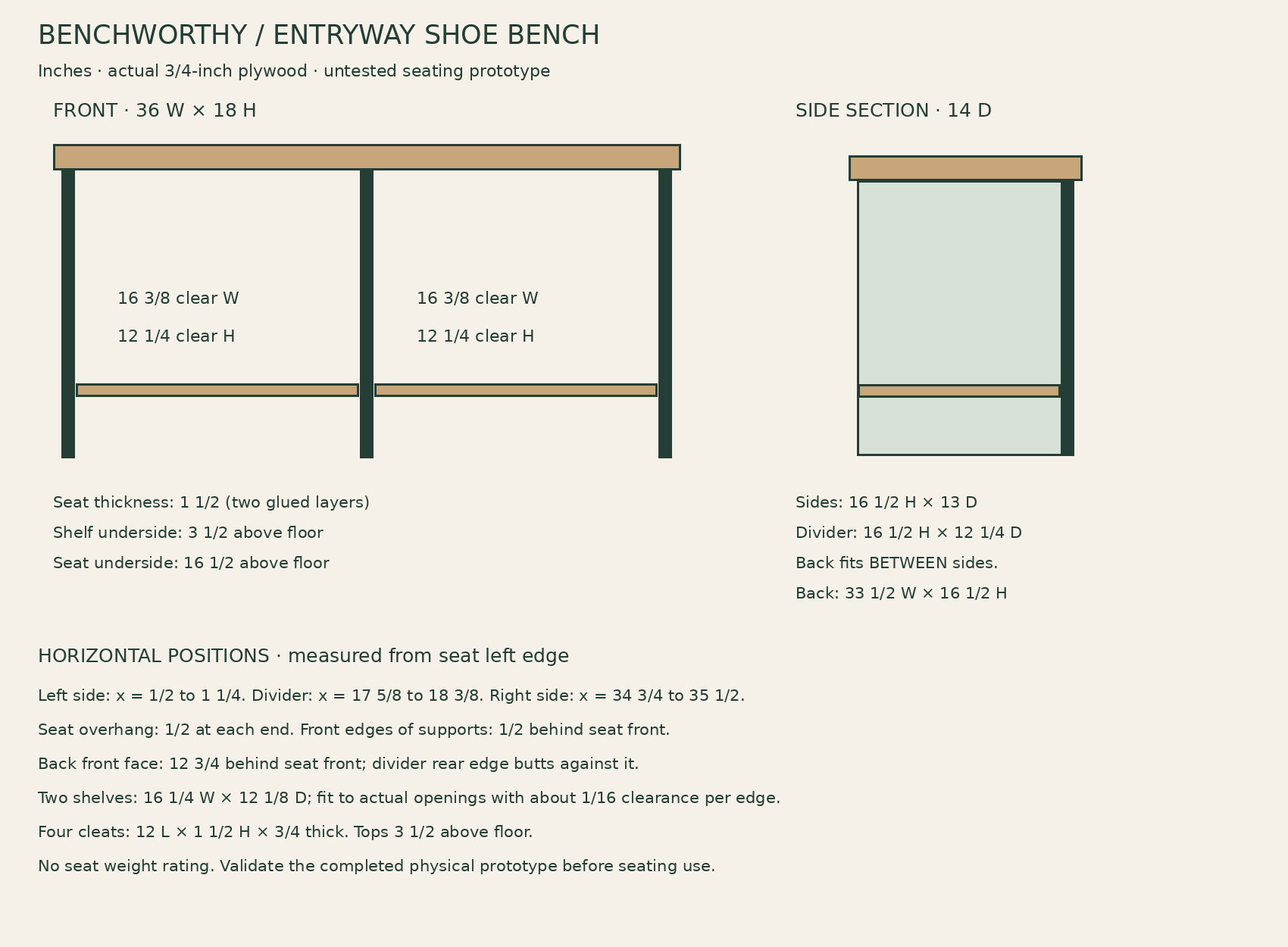
Overall size is 36 W × 14 D × 18 H inches, without a cushion or added feet. Each opening is 16 3/8 inches wide × 12 1/4 inches high above its shelf; usable depth is about 12 1/4 inches to the back. Shelf panels are slightly smaller to lift out.
Measure a pair together at the widest point, the toe-to-heel length and the boot height. Leave hand clearance. Long shoes or tall boots may need a different design; do not assume the illustration guarantees your shoe size fits.
Check the door swing and the clear walking route with a taped 36 × 14-inch footprint. Keep the bench on a flat, dry floor. Added feet or a cushion change the seat height and stability assumptions.
This is indoor furniture. Seal all panel edges and wipe wet shoes before storing them; do not let water pool on plywood.
Cut list
All dimensions are inches and assume actual 3/4-inch plywood. The cleats are actual 3/4 × 1 1/2-inch 1×2. Use sound cabinet-grade plywood with no voids at joints. Measure thickness first: side/divider height = 18 minus twice the seat-layer thickness. Back width = 35 minus twice the side thickness. Keep the divider centered and fit shelves to the actual openings.
ID
Part
Qty
Finished size
A
Seat layers
2
36 × 14 × 3/4
B
Sides
2
16 1/2 H × 13 D × 3/4
C
Back between sides
1
33 1/2 W × 16 1/2 H × 3/4
D
Center divider
1
16 1/2 H × 12 1/4 D × 3/4
E
Lift-out shoe shelves
2
16 1/4 W × 12 1/8 D × 3/4
F
Shelf cleats
4
12 L × 1 1/2 H × 3/4
Material layout: one 48 × 96-inch sheet of 3/4-inch plywood supplies the panels. Rip a 36-inch-wide strip, then lay out sequential bands: two 14-inch bands for the seat layers; a 16 1/2-inch band for the back; a 13-inch band holding two side blanks rotated to fit across the strip; a 12 1/4-inch band for the divider; and a 12 1/8-inch band holding both shelves side by side. The bands total under 84 inches including nominal 1/8-inch kerfs. Trim each part to its listed dimensions and cut the shelves after assembly. One 6-foot 1×2 supplies four 12-inch cleats with trimming allowance.
Construction drawing
Use the construction dimensions for panel positions and shelf clearance. The hero render shows intended storage use.
Glue and fasteners
Wood glue suitable for the plywood; flat clamping cauls and enough clamps for full seat-lamination contact. A gap between seat layers is not a sound lamination.
About 22 #8 × 1 1/4-inch wood screws: six retain the seat layers from below; 15 attach the shelf cleats, with a spare. Countersink underside seat screws flush so they do not obstruct the bearing panels.
Twelve #8 × 1 3/4-inch wood screws: eight through the sides into the back edges, four through the back into the divider rear edge. Predrill on the plywood centerline and avoid intersecting fasteners.
Twelve #8 × 2 1/2-inch wood screws through the 1 1/2-inch seat into the tops of the sides, divider and back. These penetrate about 1 inch into the vertical panels. Use wood screws, correctly sized pilot holes and flush heads; do not substitute drywall screws.
Finish suitable for indoor furniture, sandpaper and optional plugs for countersunk top screws. Plugs are decorative; do not enlarge the structural pilot holes to conceal them.
Build sequence
Cut A–D and the cleats. Label panel faces and keep both sides and divider the same height. Dry-fit them under the seat; all bearing edges must meet the seat underside without gaps. Sand exposed edges and lightly ease the seat edges without reducing the bearing surfaces.
Glue the two 36 × 14-inch seat layers face-to-face. Clamp between flat cauls with aligned edges. From the underside, drive six 1 1/4-inch screws at x = 6, 18 and 30 inches from the left and y = 3 and 10 inches from the front. Countersink flush and let the glue cure fully.
Assemble the back between the sides. Align all panel bottoms; the back rear face is flush with the side rear edges. Glue and clamp square. Drive four 1 3/4-inch screws through each side into the back edge at heights 2, 7, 12 and 15 inches above the bottom, centered across the back thickness.
Center the divider between the side panels, with its front edge flush to their fronts and its rear edge against the back front face. Glue that rear edge. Drive four 1 3/4-inch screws through the back into the divider rear edge at the same four heights. Measure both front openings: each should be 16 3/8 inches wide.
Install four shelf cleats: one inside each end panel and one on each face of the divider. Their tops are 3 1/2 inches above the floor. Center each 12-inch cleat along the 12 1/4-inch usable bay depth, leaving 1/8 inch at each end. Glue and fasten through the cleat face with 1 1/4-inch screws centered in its height. Use four screws per outer cleat and four on the divider’s left face, at 1 1/2, 4 1/2, 7 1/2 and 10 1/2 inches from the cleat front. Use three on the divider’s right face at 3, 6 and 9 inches from its front. This staggering prevents the opposing screws from meeting inside the thin divider. Test screw penetration in scrap first.
Set the laminated seat over the carcass with 1/2-inch overhang on all four outer edges. Panel positions measured from the seat left are: left side 1/2–1 1/4, divider 17 5/8–18 3/8, right side 34 3/4–35 1/2 inches. Their fronts are 1/2 inch behind the seat front. Confirm the back rear is 1/2 inch ahead of the seat rear.
Glue the panel tops to the seat underside and clamp. Drive three 2 1/2-inch screws down into each side and the divider, centered in their 3/4-inch edges, at y = 2, 6 1/2 and 11 inches from the seat front. Add three into the back at y = 13 1/8 inches and x = 6, 18 and 30 inches. Pilot carefully through the full seat thickness into the panel edges; these locations avoid the seat-lamination screws.
After checking squareness and allowing the joints to cure, measure each cubby. Cut its shelf about 1/8 inch smaller in width and depth than the measured opening, giving roughly 1/16-inch clearance around it. Ease the edges and rest the shelves on their cleats; they lift out for cleaning and inspection.
Apply and cure the finish. Place the bench on a flat floor and verify both ends, divider and back bear as intended without rocking. Check every joint and fastener. The completed prototype needs seating strength and stability validation before anyone sits on it.
Prototype checks before seating use
Unreviewed prototype — not build tested. The geometry, panel allocation, bearing layout and nominal screw positions have been checked digitally. Seat-lamination quality, plywood strength, edge fasteners and resistance to seating loads have not been physically validated. No person-weight capacity is claimed. Do not treat a successful dimensional fit as a seating test.
Validate the completed bench’s seat, joints and stability before seating use. Keep it out of seating service until that is complete; the concept render depicts storage, not evidence of a tested seat.
Do not stand, jump or climb on the bench or use its shoe shelves as steps. Stop use if the seat flexes excessively, a joint opens, plywood splits or the unit rocks.
Keep the two shoe shelves removable; do not count their cleats as seat support. The seat bears on the two sides, center divider and back.
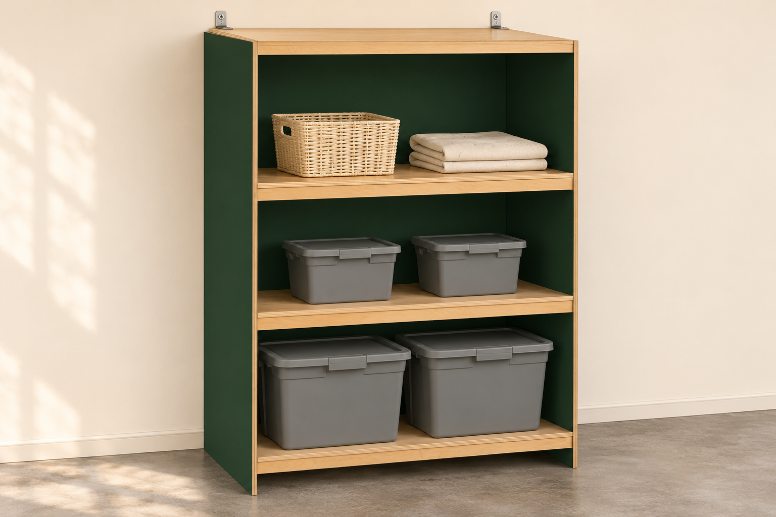
This fixed plywood shelving unit provides three open storage bays for totes, baskets and folded shop supplies. Full-height sides and a full back enclose the storage, while wood cleats support the shelf ends and glued front/rear stiffeners help the shelf decks resist bending. The fourth deck forms the top; leave it clear rather than using it for overhead storage.
The unit is 48 inches wide, 24 inches deep including its back, and 72 inches high. It stands on the floor and must be secured to wood wall studs with two compatible anti-tip restraints before use. The wall connection prevents tipping; the floor supports the cabinet’s weight. This is a dry, indoor storage prototype with no assigned load rating.
Measure your bins and installation space
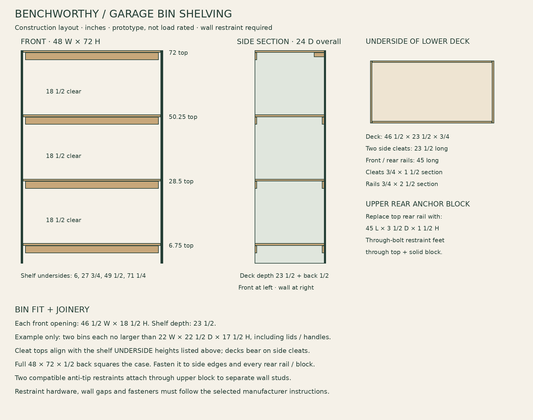
Each of the three front openings is 46 1/2 inches wide and 18 1/2 inches high beneath the front stiffener. The shelf deck is 23 1/2 inches deep. There is more height behind the front rail, but the bin still has to pass through that opening.
As a size example, two bins each up to 22 inches wide × 22 1/2 inches deep × 17 1/2 inches high leave nominal handling space. Measure the maximum outside size including lid, handles and any latch protrusions. These dimensions describe fit, not an approved bin weight or a particular tote product.
Allow space to pull bins straight out, not just room for the cabinet. Locate outlets, garage-door hardware, pipes and switches before choosing a location. Confirm two sound wood studs can be reached by the upper restraints.
Check floor level and moisture. Seal panel edges. Do not place unfinished plywood against a damp slab or use this plan outdoors. Solid full-bearing shims can correct a small floor variation; a significantly sloped garage floor needs a separately designed base. Baseboards may create a wall gap that the selected restraint system must accommodate without bending the brackets.
Cut list
All dimensions are inches and use actual 3/4-inch side/deck plywood, 1/2-inch backing, 3/4 × 1 1/2-inch 1×2 cleats, 3/4 × 2 1/2-inch 1×3 stiffeners and 1 1/2 × 3 1/2-inch 2×4 stock. Measure your materials before cutting. For a 48-inch outside width, deck length = 48 minus twice the actual side thickness. Stiffener and block length = deck length minus twice the cleat thickness. Cut decks to the dry-fitted opening if your stock differs.
ID
Part
Qty
Finished size
A
Sides
2
72 H × 23 1/2 D × 3/4
B
Shelves + top
4
46 1/2 W × 23 1/2 D × 3/4
C
Full back
1
48 W × 72 H × 1/2
D
Side cleats
8
23 1/2 L × 1 1/2 H × 3/4
E
Front / rear stiffeners
7
45 L × 2 1/2 H × 3/4
F
Upper rear anchor block
1
45 L × 3 1/2 D × 1 1/2 H
Material allocation: two full 48 × 96-inch sheets of 3/4-inch plywood and one full sheet of 1/2-inch plywood. From the first thick sheet, crosscut a 72-inch section; rip two 23 1/2-inch-wide sides from it. The remaining approximately 23 7/8 × 48-inch section yields one deck. From the second thick sheet cut three more decks, orienting their 46 1/2-inch dimension across the sheet. The thin sheet yields the 48 × 72-inch back. These layouts allow a nominal 1/8-inch kerf but little extra length for trimming the first sheet; verify usable sheet sizes before committing. The offcuts remain useful for other projects.
Three 8-foot 1×2 boards yield the eight cleats (three per board, one spare). Four 8-foot 1×3 boards yield the seven stiffeners (two per board, one spare). One 8-foot 2×4 yields the anchor block. Reject badly warped, split or knot-weakened pieces, especially the cleats and anchor block.
Drawings and shelf clearances
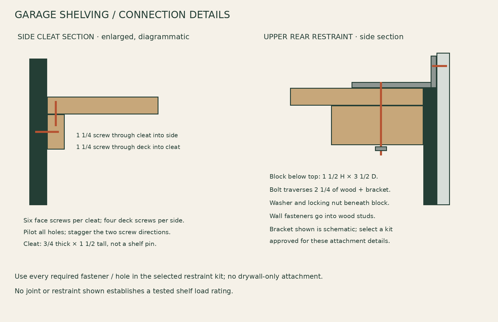
Four decks form three usable bays; shelf undersides are measured from the side-panel bottom.Connection details are schematic. Select anti-tip hardware approved for the illustrated through-bolt and wood-stud attachment.
Fasteners and restraint hardware
Approximately 80 #8 × 1 1/4-inch wood screws: 48 cleat-to-side screws (six per cleat) and 32 deck-to-cleat screws (four per shelf end). The 1 1/4-inch cleat screw passes through the 3/4-inch cleat into 1/2 inch of the side panel; test in scrap so points do not emerge.
Forty #8 × 1 3/4-inch wood screws: five per stiffener and five for the upper rear block, driven through the deck from above. Glue the full contact edges/faces before assembly. These screws draw the parts together; the narrow glued stiffener edge needs continuous contact without gaps.
Approximately 55 #8 × 1-inch screws for the back, plus wood glue. Pilot holes are especially important where screws enter the 3/4-inch side-panel edges. Keep every screw centered in the material it enters. Do not substitute drywall screws.
Two furniture anti-tip angle-bracket assemblies with a manufacturer-approved through-bolt attachment to the cabinet top and screw attachment to wood studs. The upper rear block supplies solid backing under the 3/4-inch top. Choose bracket feet that reach this block and permit fastener holes away from its edges; do not drill or modify the bracket unless permitted.
Cabinet-side bolts, large washers and locking nuts must pass through the bracket, 3/4-inch top and 1 1/2-inch block: 2 1/4 inches of wood plus hardware. Select diameter, length, hole locations and quantity to the restraint manufacturer’s instructions and use every required hole. Wood-stud screws must provide the specified embedment after drywall and any permitted spacers. The thin back alone is not a restraint attachment.
Build the shelving unit
Cut the panels and rails; label front, rear and inside faces. Check the two sides match. Mark four shelf-underside lines on both inside faces: 6, 27 3/4, 49 1/2 and 71 1/4 inches above the panel bottoms. These produce shelf tops at 6 3/4, 28 1/2, 50 1/4 and 72 inches.
Glue and screw one full-depth side cleat below each line, with its TOP on the line and its 3/4-inch-thick dimension projecting inward. Use six 1 1/4-inch screws through each cleat into the side face at approximately 2, 5.9, 9.8, 13.7, 17.6 and 21.5 inches from the front. Center these screws vertically in the 1 1/2-inch cleat height; pilot and countersink without crushing the wood.
Prepare three lower decks with one 45-inch stiffener glued beneath the front edge and one beneath the rear edge. Center each rail across the width, leaving 3/4 inch at each end for the side cleats. The 2 1/2-inch dimension hangs vertically; the 3/4-inch edge contacts the deck. Use five 1 3/4-inch screws from above per rail, spaced along its length and centered across that narrow edge. Clamp flat until cured.
Prepare the top deck with the same front stiffener. At its rear replace the narrow stiffener with the 2×4 anchor block laid FLAT: 3 1/2 inches front-to-back and 1 1/2 inches high. Its rear edge is flush with the deck rear and its ends leave 3/4 inch for each side cleat. Glue and fasten with five 1 3/4-inch screws through the top into the block, along a line about 3/4 inch from its front edge. Reserve the remainder of the block for the selected restraint bolts; lay out all holes first to avoid conflicts.
With a helper, assemble the two sides and four decks on a flat supported surface. Shelf ends sit directly on the cleats; the stiffeners fit between them. Glue the deck-to-cleat contact and fasten each deck end with four 1 1/4-inch screws from above, centered in the cleat’s 3/4-inch projection. Locate these at roughly 3, 8, 13 and 18 inches from the front to avoid the cleat face screws. Pilot and check that the two screw directions do not collide.
Compare the cabinet diagonals and clamp square before attaching the back. Glue the back to the side rear edges and the rear stiffeners/block. Screw the back into the centered side edges at approximately 8-inch spacing, keeping about 2 inches from the ends. Add six screws across each rear rail and the upper block, staying clear of deck screws and future restraint holes. Use 1-inch screws; confirm the points do not emerge through the narrow rails. The full back must be attached before standing the cabinet up.
Seal and finish all exposed surfaces and panel edges; allow glue and finish to cure. With a helper, stand the empty cabinet in place, level it and provide full-bearing support under both side-panel bottoms. Do not load the unit yet.
Locate two separate wood studs near the upper rear block. Fit both anti-tip assemblies according to their instructions. Their horizontal feet must bear on the top over the solid block, not over an unsupported part of the top. Through-bolt the cabinet side using washers and locking nuts accessible from the upper bay; attach the wall side to studs with the specified screws. Accommodate baseboards only with the hardware maker’s approved spacer or strap arrangement. Secure both restraints before use.
Confirm the cabinet is square and stable and all joints and restraints are secure. Try empty bins first. Keep the top clear; place heavier suitable contents in the lowest bay and distribute stored items rather than concentrating weight at the center.
Prototype checks and limits
Unreviewed prototype — not build tested. The geometry, material allocation and nominal fastener clearances have been checked digitally. Shelf bending, cleat connections, racking resistance and anti-tip hardware performance have not been physically tested. No shelf or cabinet load rating is assigned. The concept render demonstrates bin storage; the construction drawings and measured hardware determine the build.
Do not climb, sit or stand on the shelves. Keep children from climbing the unit. The back is for cabinet bracing; the two stud-connected restraints are still required.
Do not use this prototype for engines, batteries, bulk liquid containers, machinery or other concentrated heavy loads. A load rating requires a separate structural design and physical validation.
Inspect for sagging decks, loose cleats, splits, backing separation, floor movement and restraint loosening. Stop using the unit and unload it if any appear.
Before marking the plan build tested, assemble and check a physical prototype with the actual plywood, fasteners, floor condition, wall construction and restraint hardware.