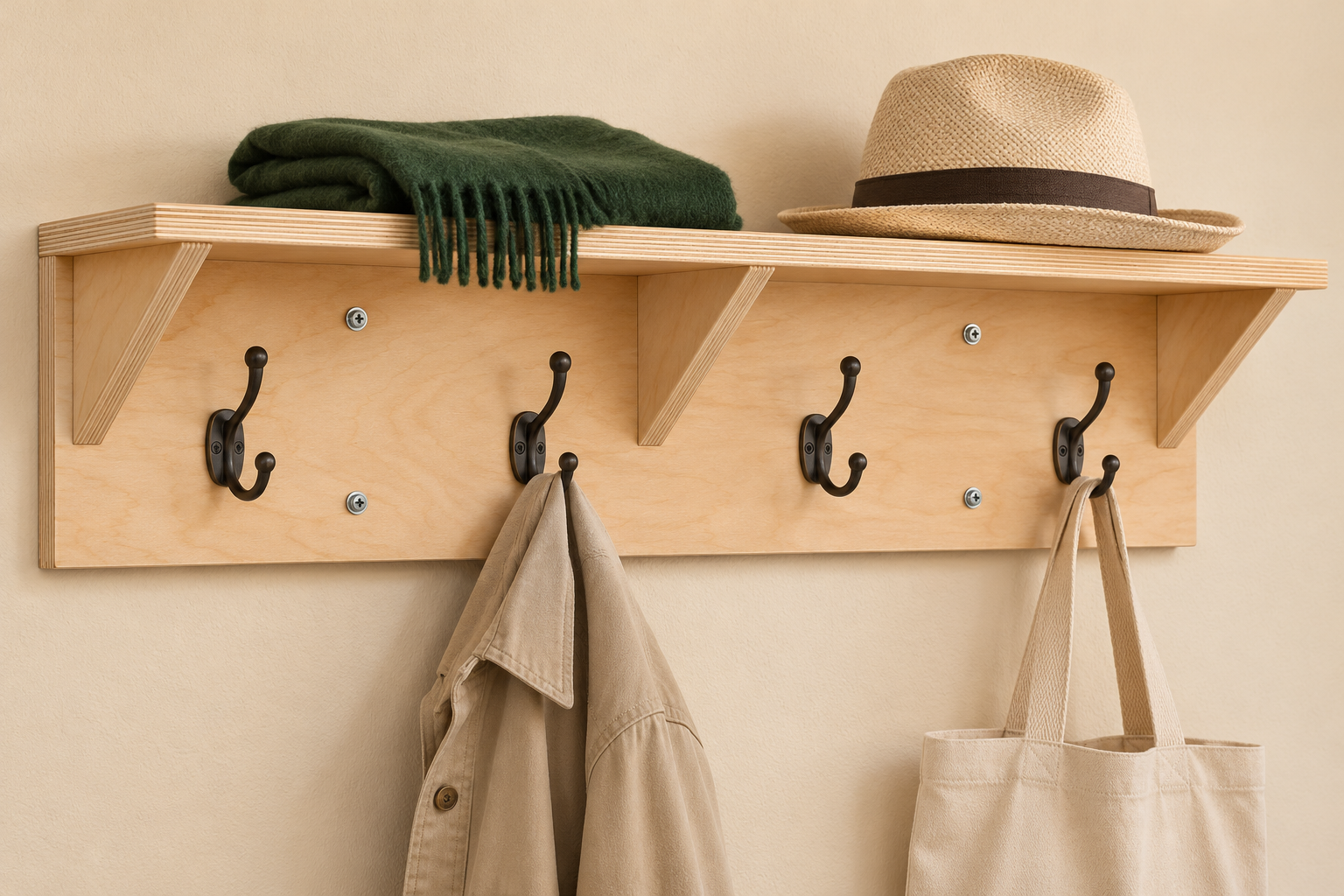
Hang four everyday coats or bags beneath a shallow shelf for hats and small entryway items. Three triangular brackets support the shelf while keeping the hook spaces open. The backboard mounts to two wood studs 16 inches apart.
Check the fit
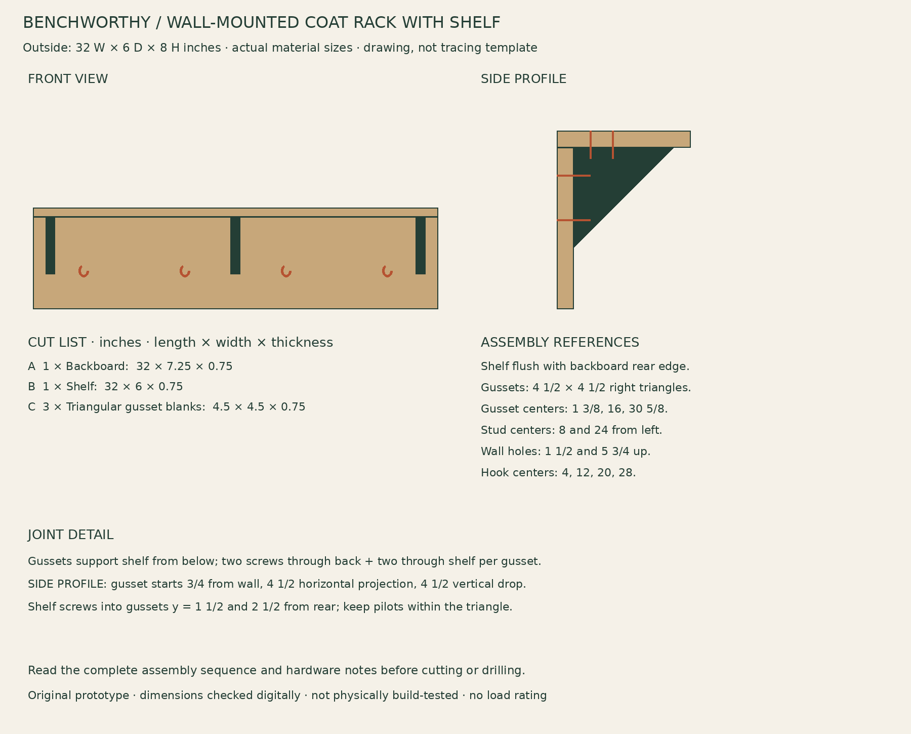
Overall 32 inches wide, 6 inches from wall to shelf front, 8 inches high. Shelf top is 3/4 inch above the backboard.
This mounting layout is for two sound wood studs at 16 inches on center behind 1/2- or 5/8-inch drywall. It does not cover hollow-wall anchors, masonry or metal studs.
Choose hook bases that fit the 7 1/4-inch backboard and have screw positions clear of the gussets and wall fasteners. Lay the actual hooks out before drilling.
Materials and tools
One 24 × 48-inch panel of actual 3/4-inch sound plywood
Four two-hole coat hooks whose bases fit below the shelf; use eight hook screws suited to 3/4-inch plywood without breaking through the back
Four 3-inch washer-head structural wood screws, selected for wood-stud mounting and the actual wall; minimum 1 1/2-inch embedment into sound studs, excluding drywall and backboard
Tools: Circular saw with guide; jigsaw for gusset diagonals; Drill/driver, pilot and clearance bits, countersink and depth stop; Clamps, square, level, tape measure and stud finder.
Cut list
Part
Qty
Length
Width
Thickness
A — Backboard
1
32 in
7.25 in
0.75 in
B — Shelf
1
32 in
6 in
0.75 in
C — Triangular gusset blanks
3
4.5 in
4.5 in
0.75 in
Drawings and connections
Use stated dimensions and actual material thickness. Concept images illustrate use; this drawing and the instructions define construction.
Shelf sits on top of the backboard, flush at the wall-side rear edge. Gussets meet the backboard front face and shelf underside. Their horizontal and vertical legs are each 4 1/2 inches.
Gusset centerlines: x = 1 3/8, 16, 30 5/8 inches from left. Glue mating faces. Two 1 1/2-inch screws enter each gusset from the BACK at z = 4 and 6 inches above backboard bottom.
Four 1 1/2-inch screws through shelf into backboard top edge: x = 4, 12, 20, 28; y = 3/8 from wall-side shelf edge. Six 1 1/4-inch screws through shelf into gussets: at each gusset centerline, y = 1 1/2 and 2 1/2 from rear. These positions stay within the triangular wood beneath.
Wall fasteners: x = 8 and 24, z = 1 1/2 and 5 3/4 inches from backboard bottom. Verify actual stud centers before drilling. Three-inch screw less 3/4 backboard and 5/8 drywall leaves 1 5/8 inches nominal stud penetration; follow the screw maker’s requirements.
Hook centerlines: x = 4, 12, 20, 28. Set actual hook bases near z = 3 inches, adjusting to their hole pattern. Do not let hook screws penetrate the wall or collide with other screws.
Assembly
Cut the plywood. Cut the backboard and shelf square. Cut three 4 1/2-inch-square blanks and divide each diagonally, using one triangle from each; keep the spare halves. Support and clamp small blanks safely while cutting.
Lay out the hardware. Dry-fit shelf, three gussets and actual hooks. Mark all screw locations from the joint notes and check interference. Do not mark hook holes from a generic drawing; use the selected hook bases.
Build the shelf assembly. Glue shelf to backboard and clamp square. Drill clearance holes through shelf and pilots into the backboard edge, then drive the four top screws. Glue gussets into position; fasten through the back first, then through the shelf. Keep heads on the rear flush so the rack seats flat.
Finish and add hooks. Allow glue cure, ease corners and sand. Apply and cure finish. Pilot hook holes with a depth stop and install the hooks using screws that fit the plywood thickness. Verify tips do not protrude from the rear.
Mount to studs. Locate and verify two sound stud centers 16 inches apart and check for services before drilling. Level the rack, transfer mounting holes and pilot as required by the structural screw maker. Fasten all four wall screws with the rack supported; do not crush the backboard. If stud spacing or wall construction differs, stop and use a separately designed mounting detail.
Check before use. Check shelf joints, hooks and all wall fasteners, then add ordinary items gradually. Stop for movement, splitting or loose hardware. Do not assign a capacity from the hook packaging alone; the entire assembly and wall connection matter.
Use and care
Do not use as a grab bar, climbing aid or support for a person.
Keep heavy or breakable objects off the shallow shelf. No assembly load rating is established.
Periodically inspect mounting screws, hook screws and gusset joints.
Build notes
This original plan has not been physically build-tested. Digital checks cover dimensions and part fit; they do not establish joint strength, load capacity or long-term performance. Check the actual materials and hardware, dry-fit before fastening, and stop use if joints loosen or parts deform.
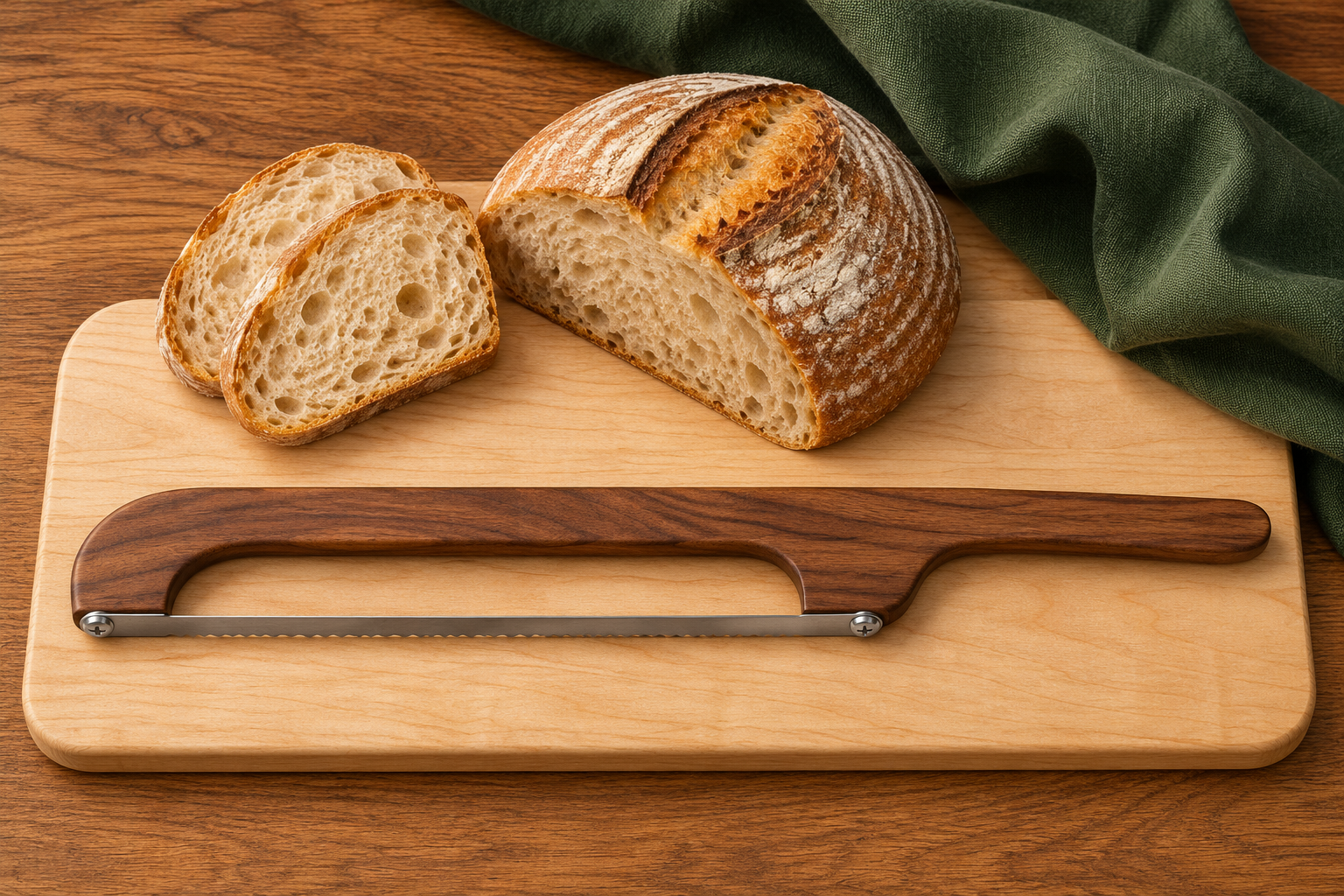
Shape a one-piece hardwood body around a purpose-made serrated bread blade. A slim, gently bowed rail leaves lateral room for the slice. The slim grip flows from the rail and tapers gently toward the blade side, with a rounded end and no stepped offset or dogleg. This is a small woodworking project for a bread-making kitchen or a handmade gift, with a replaceable commercial blade.
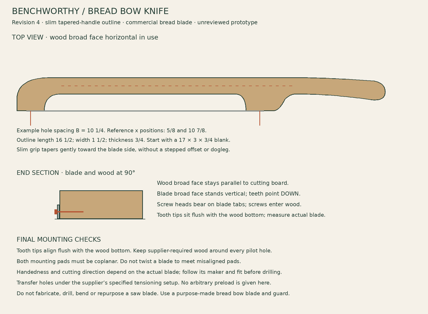
Orientation matters: the broad face of the wooden bow stays roughly parallel to the cutting board. The blade stands perpendicular to it, with teeth pointing down and the tooth tips flush with the bottom of the wood. Both supplied screws pass directly through the blade’s existing end holes into pilot holes in the narrow front edges of the wooden mounting pads; their heads bear on the metal blade tabs. The screw axes are horizontal in use; they do not go down through the broad top face. The concept render and end-section drawing show that relationship.
This is an unreviewed prototype layout. The wooden outline is provided at full size, but blade mounting, handedness and tension must be resolved with the actual hardware before cutting use. The outline is not a universal hardware pattern or a verified tensioning design.
Choose and measure the blade first
Use a purpose-made bread bow knife blade with its specified mounting screws and installation instructions. Do not substitute a bandsaw blade or modify a serrated kitchen blade. Have the hardware in hand before shaping the mounting pads.
Measure B, the mounting-hole center spacing; overall blade length; blade width; hole diameter; the distance from hole centers to the tooth tips; screw length and head shape. Hole spacing and total length are different measurements.
The example uses B = 10 1/4 inches. Schlabaugh & Sons lists a bread-knife kit with a 10.625-inch blade, 10.25-inch mounting-hole spacing and supplied stainless screws. That is a dimensional reference, not a claim that this original wooden outline is their tested kit design. Verify the current product and ask the supplier for its mounting and tensioning requirements.
Nominal pad reference positions are x = 5/8 and 10 7/8 inches from the far tip end. These locate the example span only. Final pilots must be transferred from the actual blade using its maker’s tensioning setup. Do not use those references as drill marks or stretch the whole template to fit another blade.
Check which mounting side and tooth direction suit the blade and intended handedness before drilling. The slot between bow and blade provides slice clearance, not an adjustable or calibrated thickness guide.
Hardware reference: Schlabaugh & Sons bread knife blades/kits. No purchase or brand is required; a different blade needs its own measured layout and suitable mounting instructions.
Wood and hardware list
One dry, straight-grained solid-hardwood blank, 17 L × 3 W × 3/4 inch thick, surfaced flat and parallel. The illustrated outline finishes about 16 1/2 × 1 1/2 inches in top view. Choose sound stock without cracks, knots or abrupt grain runout through the bow or pads.
One purpose-made bread bow blade, its specified screws and a properly fitting blade guard. The example blade span is 10 1/4 inches; the wood does not specify a substitute screw size.
A finish explicitly labeled by its maker for the intended wooden-utensil or food-contact use; follow application and cure directions. Keep paint and decorative coatings out of this build unless their maker approves that use.
Scrap for a full-size mock-up and any supplier-specified installation fixture. No separate turned handle or lathe is needed.
Drawings and full-size outline
Blade is edge-on in the top view. The end section shows the 90-degree mounting relationship.
Download the two-page full-size bow outline (PDF). Print US Letter landscape at Actual Size / 100%, with fit-to-page disabled. Check the 1 × 1-inch square in both directions. Overlap the pages and align both pairs of registration crosses before tracing. The template deliberately has no pilot-hole dots. Keep the mounting pads oversize until the actual blade fits.
Shape and assemble
Measure the blade and read its installation instructions first. Confirm the selected blade can mount to the narrow edges of a 3/4-inch flat wooden body with adequate wood remaining around the pilots, sound screw engagement and a tooth line flush with the bottom of the wood. If those requirements conflict, revise the body or choose a compatible documented kit before proceeding.
Print, calibrate and join the outline pages. Make a paper or scrap mock-up with a blunt blade substitute. Check that the handle feels comfortable and your hand stays behind the heel pad, away from the exposed cutting span. Orient grain along the long axis of the bow.
Trace the outline on the hardwood. Cut outside the line with a bandsaw, scroll saw or jigsaw while supporting the small blank securely. Keep extra wood at both mounting pads. Leave smooth internal curves rather than sharp re-entrant corners; do not thin the bridge or pad roots for appearance.
Sand to the outline and refine the handle. Ease grip edges by hand. Keep the two narrow blade-mounting faces flat, coplanar and unrounded where the metal blade tabs must bear. Avoid rounding those faces with a router. Do all powered shaping with the blade removed.
With the blade guarded and supported, check the actual mounting geometry. In the working orientation the wood broad face is horizontal, the blade face vertical and teeth downward. Transfer the tooth-to-hole offset to the pad edges so the tooth tips align flush with the wood bottom, while preserving the hardware supplier’s required wood edge distances. The pilot center height above the wood bottom equals the actual distance from the blade hole center to its tooth tips. Set both pads on a flat reference surface and verify the alignment with the guarded blade. Do not guess hole height from the photograph.
Use the blade supplier’s tensioning and hole-transfer method. The bow must hold the blade without sag, twist or excessive flex, but this plan does not assign a numerical preload or an end-to-end squeeze distance. Do not use screws to pull an incompatible blade into position. If the supplier gives no tensioning method, resolve that before final drilling; the outline alone does not establish safe tension.
With the blade removed, drill correctly sized pilots perpendicular to the narrow mounting faces, using a depth stop that prevents breakthrough. Test the drill and screw on a matching scrap. Screw axes are horizontal in the knife’s working orientation, not vertical through its top.
Finish all the wood with the selected utensil-compatible product, following its full cure requirements. Keep the blade removed during finishing. Reinstall using the supplied hardware and hand tools as directed; do not use an impact driver or countersink the blade holes. Fit the blade guard.
Before cutting use, physically validate blade seating, screw retention, tension, frame integrity, hand clearance and flush tooth-to-wood-bottom alignment. Check both screw heads bear directly on the metal around the blade’s existing end holes, with no wooden cap covering the ends, and seat without distorting the blade and that the blade reaches the board without the wood stopping it short. Keep the prototype out of service if any item remains unresolved.
Use, cleaning and prototype notes
Not build tested. The original wood outline, reference span and print scale have been checked digitally. Grain suitability, bow flex, blade preload, screw edge distance and retention have not been validated with a physical blade and wood prototype. Do not describe it as a tested sourdough slicer until that validation is complete.
Once validated, use on a suitable cutting board with the teeth down and the supporting hand clear of the cutting path. Let the serrations cut with controlled strokes; stop if the blade shifts, twists or loosens.
Fit the guard for storage. Do not leave the exposed blade loose in a drawer. Follow the blade and finish makers’ cleaning instructions, wipe the wood clean and dry promptly, and do not soak or put the wooden bow in a dishwasher.
Inspect the pads, bow grain, screws and blade before each use. Stop for cracks, loose fasteners, lost tension or corrosion. Replacement blades need the same dimensional and mounting checks; equal overall length alone does not establish fit.
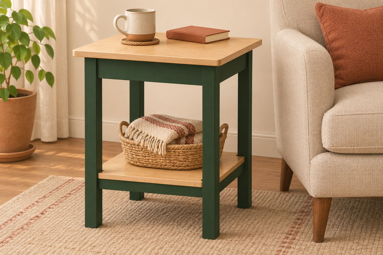
Set a drink and a book beside your chair, with a basket or spare reading material on the lower shelf. This 18-inch-square side table keeps the footprint compact and the storage open. Straight square legs and aprons give it a familiar furniture shape without drawers or complicated joinery.
The plywood top is 24 inches above the floor. A notched lower shelf rests on four rails and is fastened to them to help keep the lower frame square. Upper aprons connect the legs beneath the top. This is indoor occasional furniture; it is not a seat or a step, and no load capacity is assigned.
Check the fit beside your chair
Tape an 18 × 18-inch square beside the chair and compare a 24-inch top height with the chair arm. Confirm you can reach the surface comfortably and still walk around it.
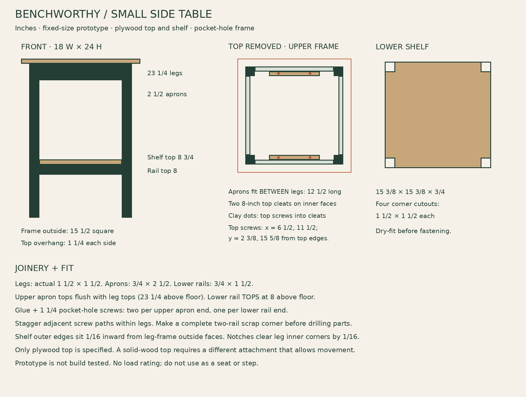
The lower shelf is 15 3/8 inches square before its corner notches. The clear front width between legs is 12 1/2 inches. Clear height from the shelf surface to the upper apron bottom is 12 inches. Choose a basket smaller than both openings, including handles, so it slides out without tilting.
This plan uses a 3/4-inch plywood top. Do not replace it with a solid-wood panel using the same fixed screw pattern; solid wood needs an attachment that permits seasonal movement.
Use dry, straight, square stock and a flat indoor floor. Added feet, a thicker top or tapered legs change the dimensions and stability assumptions.
Cut list
Dimensions are inches. Nominal 2×2 legs must measure 1 1/2 inches square. The 1×3 aprons measure 3/4 × 2 1/2; the 1×2 rails/cleats measure 3/4 × 1 1/2. Verify actual stock before cutting. Leg length = 24 minus top thickness. With the same 15 1/2-inch outer frame, rail/apron length = 15 1/2 minus twice the leg width.
ID
Part
Qty
Size
A
Top
1
18 × 18 × 3/4 plywood
B
Legs
4
23 1/4 × 1 1/2 × 1 1/2
C
Upper aprons
4
12 1/2 × 2 1/2 × 3/4
D
Lower rails
4
12 1/2 × 1 1/2 × 3/4
E
Shelf blank
1
15 3/8 × 15 3/8 × 3/4 plywood
F
Top cleats
2
8 × 1 1/2 × 3/4
Cut a 1 1/2 × 1 1/2-inch square from each shelf corner. With a 15 1/2-inch outside frame and 1 1/2-inch legs, the shelf sits 1/16 inch inside the outside leg faces, with the same nominal clearance at the notch corners. Dry-fit and adjust for actual leg dimensions; do not force the shelf between legs.
Stock allocation: one 24 × 48-inch 3/4-inch plywood panel supplies top and shelf. One 8-foot 2×2 yields four 23 1/4-inch legs with nominal 1/8-inch kerfs. One 6-foot 1×3 supplies four aprons. One 6-foot 1×2 supplies four lower rails and two 8-inch cleats. Allow extra material if ends need more squaring, defects require avoidance, or your stock is undersized.
Construction drawing
Dimensions govern construction. The in-use render shows the intended chair-side storage.
Hardware and pocket-hole setup
Twenty-four 1 1/4-inch pocket-hole screws: sixteen for the upper aprons and eight for the lower rails. Match screw thread to the receiving leg species and follow your jig manufacturer’s settings for actual 3/4-inch material. These are pocket-hole screws with the correct head shape, not ordinary countersunk wood screws.
Eighteen #8 × 1 1/4-inch wood screws: six cleat-to-apron screws, four top-to-cleat screws and eight shelf-to-rail screws. Glue for all frame joints, shelf-to-rail contact and cleat attachment.
Pocket-hole jig, stepped bit, stop collar and driver, plus a joint clamp. Drill on the inside faces. Adjacent rails meet within the same 1 1/2-inch leg, so their screws must be staggered vertically and checked in a complete scrap corner before drilling the parts.
For upper aprons, lay out two hole axes per end. Suggested vertical exit positions are 1/2 and 1 1/2 inches below the top on one opposing pair, and 1 and 2 inches below the top on the adjacent pair. Lower rails use one axis per end, 1/2 inch below the rail top on one opposing pair and 1 inch below on the other pair. Reposition the jig as needed, keep pockets within the rail edges and confirm the actual paths do not meet.
If your jig cannot make these staggered holes cleanly within the stock, stop and revise the joint layout before assembly. A scrap test must show seated screws without split edges, breakthrough or collision.
Manufacturer reference: Kreg pocket-hole setup and screw guidance. Use the instructions for your own jig and actual material; a screw-size chart does not validate this table’s strength.
Build sequence
Cut the four legs together to matching length with square ends. Cut and label the upper aprons, lower rails and cleats. Sand now while the inside faces are accessible. Mark which opposite rail pairs receive each staggered pocket-hole layout.
Make a full scrap corner with two rail ends and a matching leg. Test the jig settings, screw length and staggered entry paths. Inspect for collision and breakthrough. Once the corner works, drill all frame pockets on their inside faces.
Build two opposite side assemblies first. Glue and clamp an upper apron between each leg pair, with its outside face flush to the leg outside faces and its top flush to the leg tops. Glue and attach the lower rail in the same plane, with its TOP 8 inches above the leg bottoms. Drive the pocket screws while the joints are held firmly against a flat reference.
Join these side assemblies with the remaining two upper aprons and two lower rails. Keep each outside face flush with the adjacent leg faces. Confirm the outer frame is 15 1/2 inches square, compare diagonals and clamp square while driving screws. The two lower rail pairs must meet at the same top height. Let the glue cure.
Cut the plywood shelf blank and its four corner notches. Ease the cut edges. With the table top still off, lower the shelf over the legs onto the four lower rails. Check about 1/16-inch clearance from the outside frame faces and around each notch. Trim only as needed so the shelf lies flat without forcing the frame out of square.
Glue the shelf-to-rail contact and add two 1 1/4-inch screws down through the shelf into each rail, centered in the rail’s 3/4-inch thickness and placed away from the pocket screws near its ends. Nominal screw centers are 7 and 11 inches from the tabletop’s left edge on front/rear rails, and 7 and 11 inches from its front on the side rails; use the corresponding shelf position as a reference. Predrill and countersink flush.
Attach one 8-inch cleat to the inside of the front upper apron and one to the rear. Center them along the apron length, with their tops flush with the apron tops. Orient each cleat 1 1/2 inches tall and 3/4 inch thick. Glue and use three 1 1/4-inch face screws per cleat, centered vertically and clear of apron pocket screws. Confirm the tips stay within the apron.
Set the 18-inch plywood top on the frame with 1 1/4-inch overhang on every side. Clamp in place. Drive four 1 1/4-inch screws from above into the top cleats at x = 6 1/2 and 11 1/2 inches from the top left, paired with y = 2 3/8 and 15 5/8 inches from the front. Pilot and countersink flush. Do not drive screws down into unsupported gaps.
Ease the top edges and apply the indoor furniture finish. Allow the finish and glue to cure. Place the table on a flat surface; check all four feet contact the floor, the frame is square and the shelf and top are secure. Use coasters to protect the plywood finish.
Prototype checks and limits
Unreviewed prototype — not build tested. Overall dimensions, cut allocation, shelf-notch clearances and nominal joint layouts have been checked digitally. Pocket-hole paths depend on the actual jig and must be checked in scrap. Joint stiffness, shelf performance and tipping resistance remain untested. No load rating is assigned.
Use only as a small occasional table after checking the physical build for stability. Do not sit, stand or climb on it, or use it to support machinery or heavy concentrated loads.
Keep stored objects within the top and shelf outlines. A small tall table can tip if pulled or heavily loaded at an edge; keep it away from uses where someone would rely on it as a support while standing up.
Inspect for rocking, loose screws, opening joints, split legs and shelf separation. Stop use if these appear. A physical prototype is still required before this plan can be marked build tested.
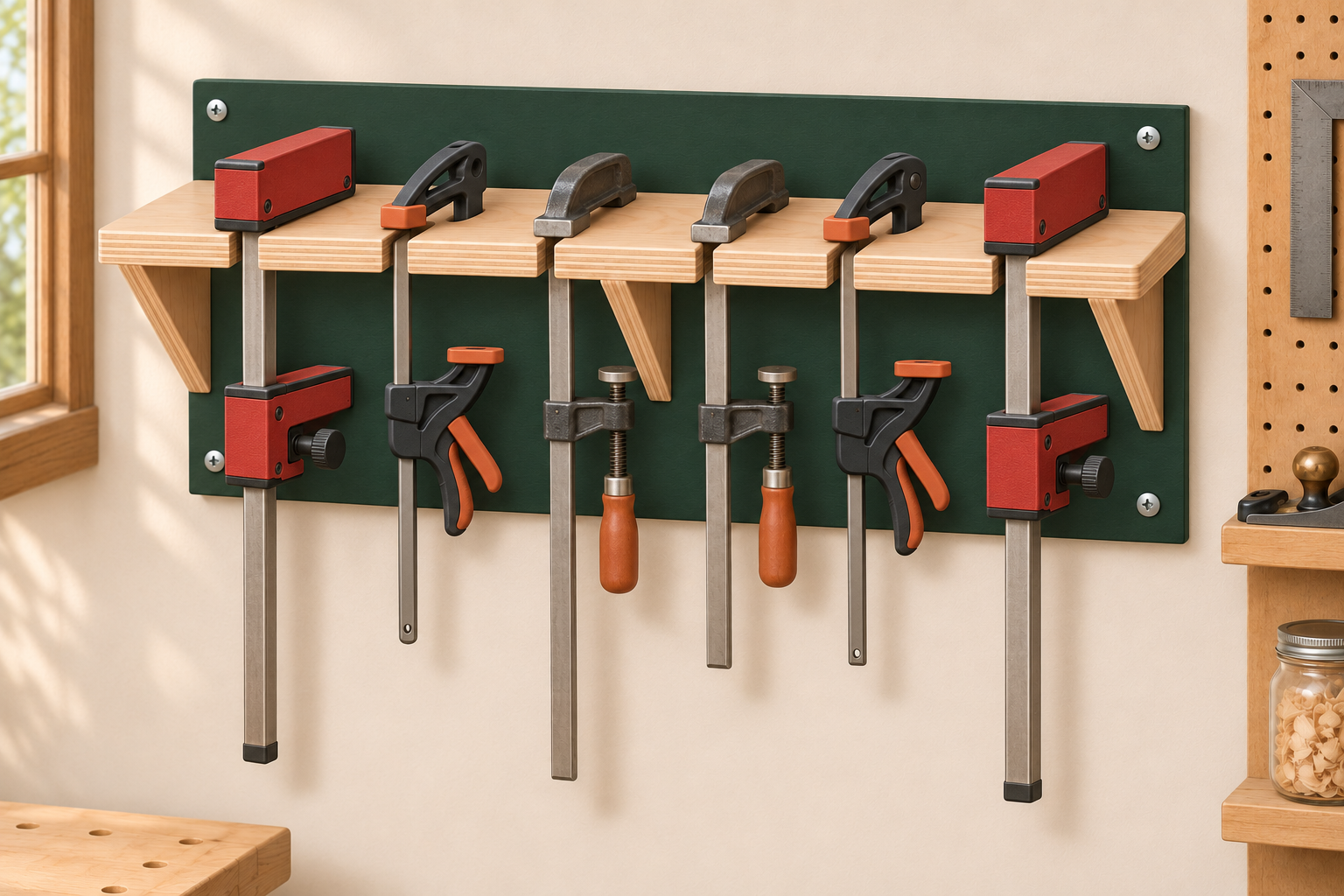
This wall-mounted rack stores six compatible F-style bar clamps individually. Slide each bar into an open-front slot; its upper fixed jaw rests on the shelf while the bar and movable jaw hang below. You can take one clamp without unpacking a pile, and empty slots show what is missing.
A double-thickness plywood shelf is supported by three triangular gussets. The backboard spans two studs on 16-inch centers. Allow clear wall space below for the longest clamp and enough space above to lift each clamp free. The rack is storage, not a surface to tighten clamps against.
Test your clamps first
The updated hero illustration shows a mixed-clamp storage concept. The current construction dimensions are for compatible F-clamps; parallel and quick clamps require separate slot-fit and support validation. This version is for smaller F-style clamps with a flat steel bar no more than 1/4 inch thick in the slot-width direction. Orient the bar’s broad face front-to-back. The 3/8-inch slot provides clearance; it is not a universal clamp holder.
The fixed head must bridge the slot with at least 1/4 inch of bearing on each side: at least 7/8 inch of solid head width across the slot. Irregular, rounded or sloping heads may not seat safely even when that width fits.
Make one 3/8-inch slot in a 1 1/2-inch laminated scrap first. Check the actual head sits flat, the bar slides without force, and the clamp can lift out without catching. Test all clamp models you intend to store.
Slot centers are 4.8 inches apart. Check adjacent jaws and handles do not collide and that the head clears the backboard. Use fewer slots if needed; do not widen slots or lengthen them without redesigning the rack. Pipe clamps, large parallel-jaw clamps, spring clamps and quick-grip shapes are outside this plan’s fit assumptions.
Cut list
Dimensions are inches and assume actual 3/4-inch plywood. Use sound, void-free plywood around slots and fasteners. A 24 × 48-inch project panel can supply these parts if its usable dimensions and trimming allowance permit; lay out all cuts before sawing.
ID
Part
Qty
Size
A
Backboard
1
32 × 10 × 3/4
B
Shelf layers
2
32 × 6 × 3/4
C
Gusset blanks
3
4 1/2 × 4 1/2 × 3/4; cut diagonally
Use one triangle from each gusset blank; keep the other halves as spares. For a 24 × 48 panel, crosscut a 32-inch-long section and rip the 10-inch back and two 6-inch shelf layers from its 24-inch width (22 inches plus kerfs). The remaining approximately 15 7/8 × 24-inch section supplies the gusset blanks. Confirm saw kerf and actual panel size first.
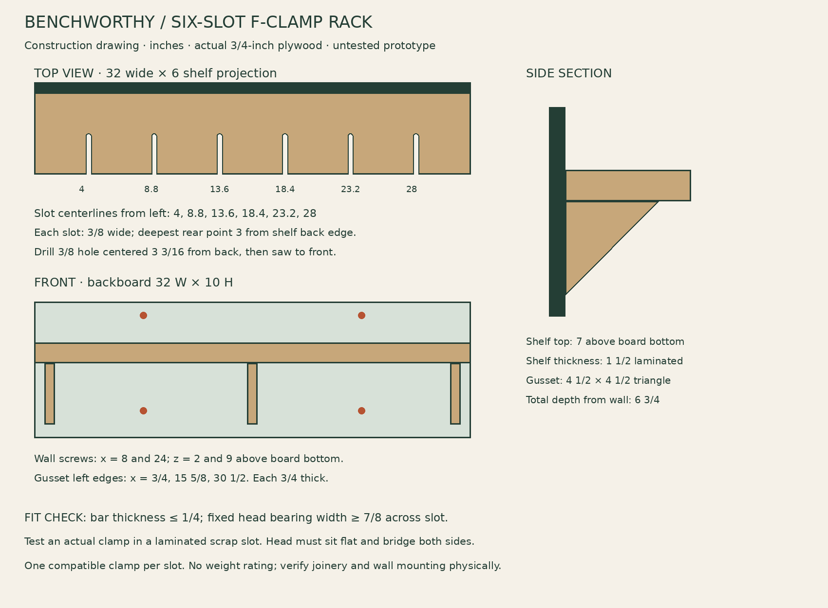
Construction drawing
Construction dimensions take precedence over the concept render.
Hardware and wall mounting
Wood glue; six #8 × 1 1/4-inch wood screws to retain the shelf laminations while gluing; nine #8 × 1 3/4-inch screws through the back into gussets; nine #8 × 2 1/2-inch screws through the shelf into gussets; six #8 × 1 3/4-inch screws through the back into the laminated shelf rear edge. Use suitable wood screws and pilot holes; do not substitute drywall screws.
Four washer-head structural wood screws approved by their manufacturer for attachment to wood studs, with at least 1 1/2 inches of stud penetration after the 3/4-inch backboard and wall finish. For 1/2- to 5/8-inch drywall, 3-inch screws provide 1 5/8 to 1 3/4 inches of geometric penetration; confirm the selected product’s installation requirements and usable threaded embedment.
The illustrated wall has sound wood studs 16 inches on center with drywall no thicker than 5/8 inch. Mount screw columns at 8 and 24 inches from the board’s left edge, with rows 2 and 9 inches above its bottom. Verify stud centers and hidden services before drilling. Do not use drywall-only anchors. Masonry, metal studs, different spacing or damaged walls need a separate attachment design.
Build and install
Cut and label all blanks. Cut three right-triangle gussets, each with 4 1/2-inch perpendicular legs. Sand sharp edges. Keep the square edges flat so the gussets bear against both back and shelf.
Glue the two shelf layers face-to-face, aligning their edges. Clamp flat with cauls. Add six 1 1/4-inch screws from the underside at x = 2, 16 and 30 inches, in rows 1 and 2 inches from the rear. Predrill and countersink flush; these positions clear the slots and gussets. Allow the glue to cure before cutting slots.
Mark the six slot centerlines 4, 8.8, 13.6, 18.4, 23.2 and 28 inches from the left edge. Drill a 3/8-inch through-hole at each centerline, with its center 3 3/16 inches from the shelf’s rear edge. Saw two parallel lines from the front edge tangent to each hole, making a 3/8-inch-wide open slot. The deepest slot point is 3 inches from the rear. Support the work and use a blade suitable for the 1 1/2-inch thickness. Smooth the slots without enlarging them.
On the backboard front, mark a line 5 1/2 inches above the bottom: this is the shelf underside. Mark gusset left edges at 3/4, 15 5/8 and 30 1/2 inches from the left. Each gusset’s upper horizontal leg aligns with that underside line, and its rear vertical leg runs down to 1 inch above the board bottom. Dry-fit and clamp the assembly square.
Glue each gusset rear edge to the backboard. Drive three 1 3/4-inch screws through the back into each gusset edge, centered on its 3/4-inch thickness, at heights 2 1/4, 3 1/4 and 4 1/2 inches above the board bottom. Use correctly sized pilots and keep screw axes straight in the plywood edges. Let the glue cure with the supports clamped square.
Glue the shelf onto the gussets with its rear edge against the backboard. Its top is now 7 inches above the backboard bottom. Drive three 2 1/2-inch screws down through the shelf into each gusset, centered across the gusset thickness, at 1 1/2, 2 1/2 and 3 1/4 inches forward of the shelf rear edge. Avoid the previously installed rear screws; the stated screw positions occupy different depths. Add six 1 3/4-inch screws through the back into the shelf rear edge at x = 2, 7, 12, 20, 25 and 30 inches, centered vertically in the 1 1/2-inch shelf thickness.
Ease edges, finish and allow glue and finish to cure. With a helper supporting the empty rack, locate the two stud centers, level the rack and mark the four mounting holes. Drill clearance holes through the backboard and stud pilots according to the structural screw manufacturer. Fasten all four screws securely without crushing the plywood or wall finish.
Try each intended clamp separately, supporting its weight by hand as you check seating and clearance. Store one clamp per slot, with the fixed head resting flat across both sides. Keep the full hanging length clear of benches, doors, outlets and walkways.
Prototype checks and limits
Unreviewed prototype — not build tested. The part layout, slot clearances and nominal screw locations have been checked digitally. Shelf fingers, glued joints, plywood edge fasteners and wall attachment have not been physically load tested. Six slots describe storage positions, not a weight rating. The concept render explains how the clamps hang; use the drawing for shelf height, slot geometry and mounting positions.
Inspect for split slot fingers, plywood voids, loose joints and wall movement before adding clamps. Stop using the rack if any part flexes, cracks or loosens.
Do not stand on the shelf, add a second row, stack clamps in a slot or use it for active clamping. Keep heavy or incompatible clamps on a separately designed support.
A physical prototype and wall-attachment verification are still required before this plan can be marked build tested.
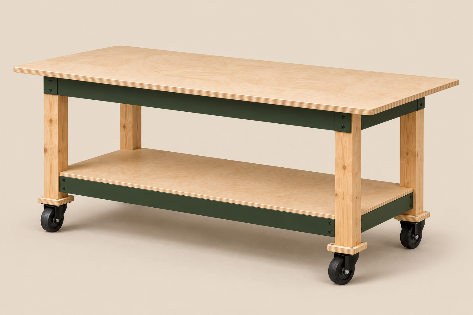
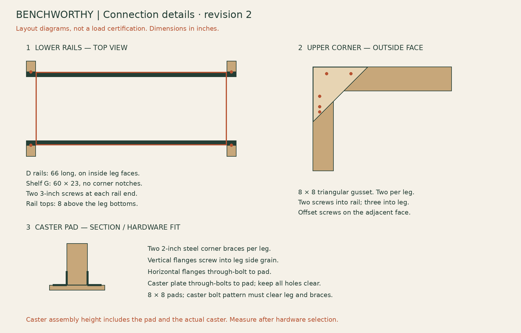
Revision 2 · untested prototype. This version specifies the connections and fastener schedule, simplifies the shelf, and adds cutting and joint drawings. It has not been physically build tested. Use the drawings for construction; the cover rendering is an illustration.
A mobile table with room to clamp
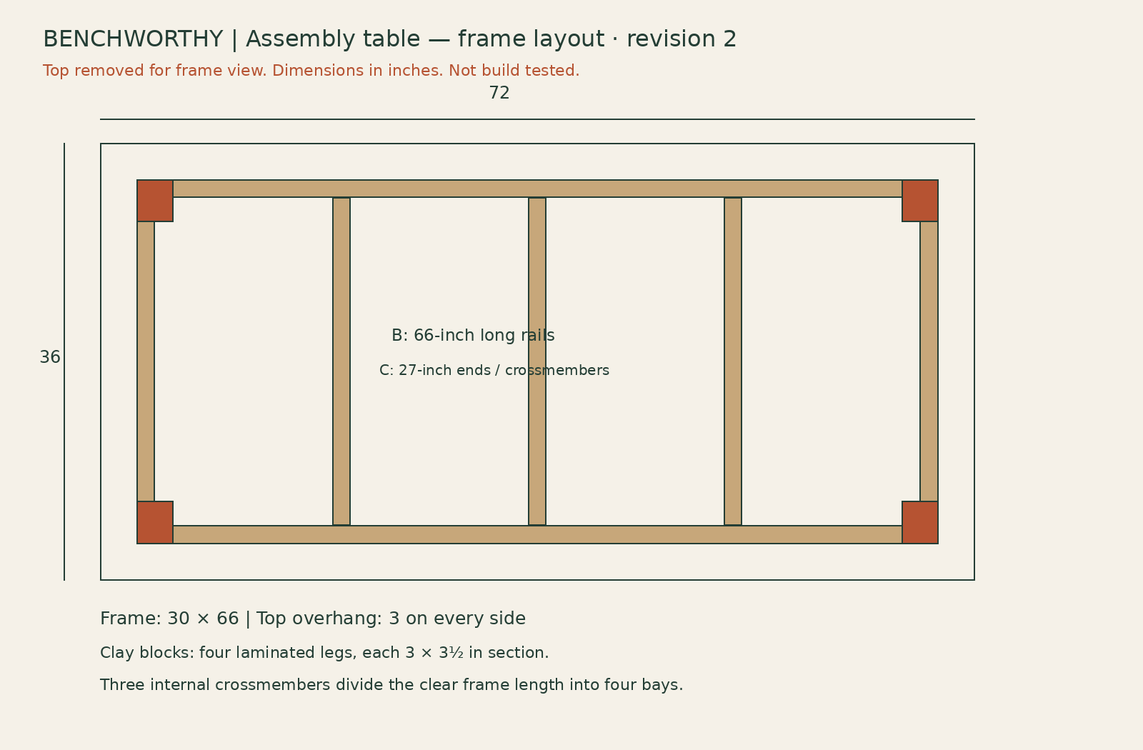
A 36 × 72-inch plywood top sits on a 30 × 66-inch upper frame, leaving 3 inches of overhang on every side. The default finished height is 34 inches, including your caster assemblies. Four legs are laminated from pairs of 2×4s. Two lower rails attach directly to the inside faces of the legs and support a rectangular 60 × 23-inch shelf—no shelf notches or special rail-end connectors.
Choose and measure the caster assemblies
Use four matching plate-mounted swivel casters with both wheel and swivel locks. Each mounts beneath an 8 × 8-inch plywood pad. The leg bears on the pad; two steel corner braces connect the pad to opposite side-grain faces of the leg. This avoids relying on screws driven into the leg’s end grain to retain the pad.
Select the caster and corner braces together before cutting the legs. Use 2-inch-leg steel corner braces with two usable holes per flange. Check that the horizontal flanges fit within the pad. On a full-size paper layout, mark the 3 × 3½-inch leg footprint, the two brace footprints, and the caster plate. Select a caster bolt pattern whose heads, washers and tool access clear the leg and braces. A plate that cannot satisfy that layout is incompatible with this mounting detail; do not enlarge holes or weaken the leg to force a fit.
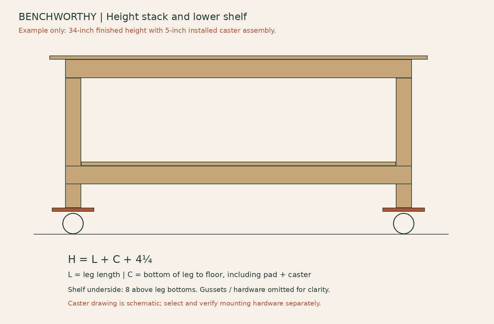
The installed caster assembly height is the distance from the bottom of the wooden leg to the floor. Include the pad thickness, mounting plate, swivel assembly and wheel. Enter that measured height in the calculator. Wheel diameter is not the installed height. All four assemblies must have the same installed height.
Calculate the legs
The upper frame rests on the leg ends. With actual 3½-inch-deep rails and a ¾-inch top, the construction above the legs totals 4¼ inches. Leg length = finished height − installed caster assembly height − 4¼ inches. If your material differs, use the actual combined rail depth and top thickness in a manual calculation; the on-page calculator assumes the specified 4¼-inch stack.
Example: a 34-inch finished table with a 5-inch installed caster assembly needs eight 24¾-inch leg components. A 6-inch assembly reduces those components to 23¾ inches. Choose and measure hardware before batching those cuts.
Outfeed mode targets a surface ⅛ inch below your equipment’s work surface. For 35-inch equipment and 5-inch caster assemblies: finished table height is 34⅞ inches and leg length is 25⅝ inches. Confirm the appropriate clearance, miter-bar path, fence movement and support position for your actual equipment.
Cut list
Actual finished dimensions in inches. “2×4” means actual 1½ × 3½-inch stock here. Part A is calculated; all other parts are fixed. Four J square blanks produce eight triangular gussets. The part IDs match the live cut list.
ID
Part
Qty
Length × width × thickness (in)
A
Leg lamination
8
Calculated × 3½ × 1½
B
Upper long rail
2
66 × 3½ × 1½
C
Upper ends and crossmembers
5
27 × 3½ × 1½
D
Lower shelf support rail
2
66 × 3½ × 1½
F
Top panel
1
72 × 36 × ¾
G
Shelf panel
1
60 × 23 × ¾
H
Caster mounting pad
4
8 × 8 × ¾
J
Gusset square blank
4
8 × 8 × ¾; cut diagonally
Materials and fasteners
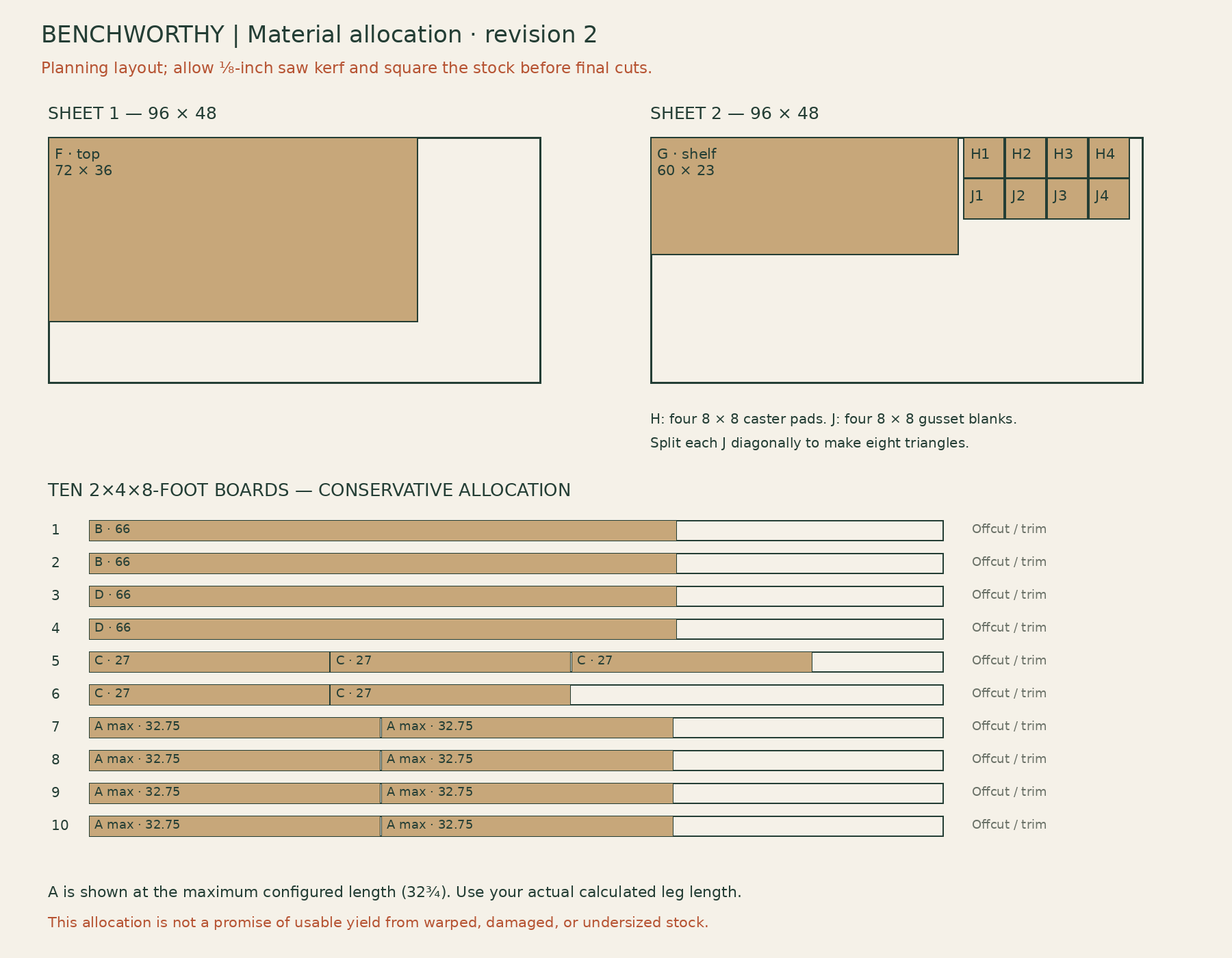
Allow ten straight 2×4×8-foot boards and two nominal 4×8 sheets of ¾-inch plywood. Inspect for twist, splits and damage; the layout is a purchasing allowance, not a guarantee of yield from defective stock. Use wood glue for the leg laminations and multipurpose wood screws intended for wood construction, rather than drywall screws.
Connection
Specification
Installed quantity
C ends to B rails
Two #10 × 3-inch wood screws at each of ten rail ends
20
D rails to leg side grain
Two #10 × 3-inch wood screws at each of four overlaps
8
Eight J gussets
Five #8 × 1¾-inch wood screws per triangle
40
F top to frame
#8 × 1¾-inch countersunk wood screws
12
G shelf to D rails
#8 × 1¼-inch wood screws
8
Corner braces to leg side grain
Two #10 × 1½-inch wood screws per brace, subject to brace-hole compatibility
16
Corner braces to pads
Two machine bolts per horizontal flange, with washers and locking nuts; size to brace holes and measured stack
16
Caster plates to pads
Four through-bolts per caster, with washers and locking nuts; size to caster instructions and measured stack
16
Buy approximately 50 of the 3-inch wood screws, 75 of the 1¾-inch wood screws, and 25 each of the 1¼- and 1½-inch wood screws. Add eight steel corner braces and four casters. Select the 32 machine-bolt assemblies only after laying out the actual hardware. Include washers under heads and nuts where the hardware permits, and enough bolt length for full locking-nut engagement. Keep bolt heads outside the leg’s bearing footprint; all hardware must clear the swivel and brakes.
Cutting layout
Boards 1–2: one B from each. Boards 3–4: one D from each. Boards 5–6: split the five C parts as three and two. Boards 7–10: two A parts per board. The layout accommodates a ⅛-inch kerf and the maximum configured 32¾-inch leg length. Shorter legs leave larger offcuts.
Sheet 1 supplies the top. Sheet 2 supplies the 60 × 23-inch shelf plus four caster pads and four gusset squares. Square and measure the sheets before laying out final cuts. The diagram includes separation for kerfs; keep defects out of the leg connections and caster pads.
Connection details
Assembly sequence
1. Lay out the hardware and record the height. Complete the caster-pad paper layout above. Measure the assembled pad-and-caster height. Select standalone or outfeed mode and write down the calculated leg length. Confirm actual lumber dimensions and plywood thickness before trusting the numbers.
2. Cut and label. Cut B, C, D and the plywood blanks. Cut all eight A laminations to one checked stop setting. Make a sample cut and measure it before batching. Rip and crosscut the shelf to fit between the legs; if the actual opening is tighter, trim only the clearance needed for a slip fit.
3. Glue the legs. Pair A pieces broad face to broad face to form four 3 × 3½-inch legs. Use an even glue layer, align both ends, and clamp against a flat reference until cured according to the adhesive instructions. A twisted lamination makes the entire table harder to square.
4. Assemble the upper frame. Position two C end rails between B long rails. All members stand on their 3½-inch edge. Check a 30 × 66-inch outside rectangle, equal diagonals and no twist. Fasten each C end with two 3-inch screws through B. Put the screw centers about ⅞ inch from the top and bottom edges of B. Use the screw maker’s pilot and countersink guidance, especially near ends and in split-prone stock.
5. Add the crossmembers. Fit the other three C pieces between B. With 1½-inch rail thickness, four equal clear bays are 14⅝ inches. Clamp each crossmember square, then use two 3-inch screws through B into each end. Recheck the diagonals and frame twist after fastening.
6. Seat and brace the legs. Place the frame upside down on a flat surface. Orient the leg’s 3-inch dimension along the 66-inch direction and its 3½-inch dimension along the 30-inch direction. Set each leg end directly against the underside of the frame at a corner, with the outside faces aligned. Add two J triangles per corner on adjacent outside faces. Align the triangle’s 8-inch horizontal edge with the frame top and its vertical edge down the leg. Each gets two 1¾-inch screws into the rail and three into the leg. Keep screws clear of the triangular edges and stagger positions on adjacent faces so the screws do not intersect. The frame bears on the leg ends; the gussets retain and brace the connection.
7. Install the lower rails. Mark a line 8 inches up from the bottom of every wooden leg. Set the top of each D rail on that line, against the inside faces of the two legs on one long side. The 66-inch rail overlaps each end leg by 3 inches. Use two 3-inch screws through the rail into each leg, centered within that overlap, approximately ¾ inch below the rail top and ¾ inch above its bottom. These screws enter leg side grain. Repeat on the other side; check the diagonals and squareness before tightening fully.
8. Install the caster pads. Center H beneath each leg. Fit two corner braces on opposite leg faces with their horizontal flanges resting on the pad. Drill the pad holes from the actual brackets, deburr the holes, and through-bolt those flanges with washers and locking nuts. Fasten the vertical flanges to leg side grain with compatible 1½-inch wood screws. The wooden leg must bear flat on the pad; no bolt head or washer may sit between them. Check the layout before drilling any caster holes.
9. Bolt on the casters. Through-bolt each caster plate to its pad using four bolt assemblies sized to the caster’s instructions. Tighten locking nuts without crushing the plywood. Turn each caster through its full sweep and operate its locks to check clearance. Re-measure from the leg bottom to the floor; if it differs from the value used to cut A, resolve that discrepancy before continuing. Fit all four casters, then turn the table upright with assistance.
10. Fit the shelf. Set G on the two D rails between the legs. It should rest on both rails with a slip fit, not force the legs apart. Install four 1¼-inch screws along each supported shelf edge. Position the screw line over the middle of the 1½-inch rail thickness. Keep unsupported shelf ends free of unnecessary holes.
11. Attach the top. Center F for 3 inches of overhang on every side. Drive six 1¾-inch screws down through the top into each long B rail. With the top’s 72-inch direction as X, suitable positions are X = 9, 18, 27, 45, 54 and 63 inches; the two screw lines are 3¾ inches in from the long edges. Check those locations against the actual frame and other fasteners. Set heads flush, not deeply buried, and leave the top unglued so it can be replaced.
12. Inspect the prototype. Check the finished height on the intended floor with all locks set. Inspect every pad, brace, bolt and screw, and check for rocking or racking before use. Recheck fasteners after initial movement. For outfeed, confirm clear travel with the equipment isolated before using it for support.
Finish and maintenance
Ease exposed edges and sand splinters. If desired, apply a finish suitable for your shop use, keeping it out of glue joints before assembly. Let it cure before glue-ups. Replace a damaged top or caster pad rather than relying on finish to strengthen it. Periodically check locks and fasteners.
Prototype notes
Revision 2 replaces the original four lower stretchers with two side-grain-fastened shelf rails. The shelf is now rectangular and the caster pads are 8 × 8 inches. Do not combine the old shelf, pad dimensions or rail lengths with this revision.
The dimensions and part relationships have been checked digitally, but the mounting hardware has not been purchased or physically fitted, and the table has not been built. No load rating is established. The configured height and caster ranges describe geometry, not tested performance. Prototype checks still include racking, shelf deflection, lock performance, mounting-pad stiffness, hardware clearance, and actual outfeed fit.
Fastener reference: GRK’s multipurpose screw information. Follow the instructions for the actual fasteners, brackets and casters you select; the reference is not a certification of this table.